
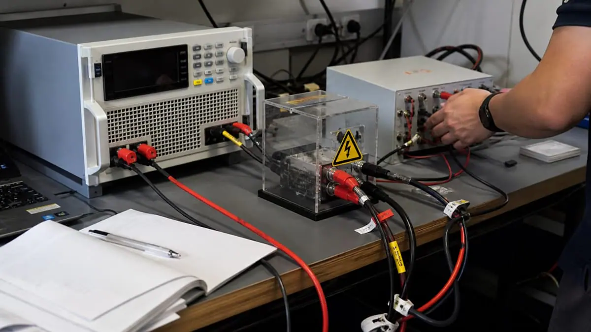
In brief
A battery test system quote should define the full voltage, current, power, channel, regenerative, cooling, communications, safety, reporting, and acceptance envelope so the supplier can scope a system rather than estimate parts.
Key takeaways
- Identify the battery or power interface, operating envelope, channel count, duty cycle, cooling, and communications before equipment is selected.
- Specify regeneration, facility energy handling, emergency states, interlocks, and safe shutdown as part of the base scope.
- Require a known-good run, a forced-fail state, a communication-loss or interlock check, and traceable pass/fail reporting.
- Include destination, end user, end use, and technical scope early when the system may be exported.
A useful battery-test RFQ is a design basis, not a shopping list. It tells the integrator what energy can enter the bench, what energy can return from the device under test (DUT), which states are permitted, how a hazardous state is removed, and what evidence will prove the delivered system is fit for the intended method. A request that says only “battery cycler, 500 V” leaves the most consequential engineering questions unanswered.
The quotation should separate three boundaries. The DUT boundary describes the cell, module, pack, battery-management system (BMS), or power-conversion interface. The test-system boundary covers sources, loads, measurement channels, contactors, discharge paths, fixtures, controls, and data. The facility boundary covers incoming power, returned energy, cooling, ventilation, protective earth, emergency isolation, access control, and local operating rules. Suppliers can price equipment only after all three are visible.
Build the electrical envelope from operating points
Do not multiply the highest voltage by the highest current unless those values occur together. For each recipe step, instantaneous DC power is P = V x I, where V is the DUT-terminal voltage and I is signed current. Choose and document one sign convention; for example, positive current may mean energy delivered to the battery and negative current may mean energy returned by it. The required source and sink envelopes are the union of all valid (V, I) points, not a single rectangular headline rating.
Energy also matters. For sampled data, a practical estimate is E = sum(V_k x I_k x delta_t_k), with consistent units and a sign convention that distinguishes charge from discharge. The RFQ should state whether energy is required merely for engineering trending or as a controlled acceptance measurand. That distinction changes sampling, timebase, calibration, correction, and uncertainty requirements.
Provide, at minimum:
- minimum, nominal, and maximum DUT voltage, including permitted overshoot and the voltage present after contactors open;
- continuous and peak charge and discharge current, pulse duration, repetition rate, rest time, and total profile duration;
- continuous and transient power at the actual voltage points where each limit applies;
- cell, module, pack, or DC-bus topology; channel count; isolation between channels; and whether channels may be paralleled;
- expected stored energy, chemistry, manufacturer operating region, thermal limits, coolant conditions, and environmental chamber interface;
- connector, polarity control, cable length, remote-sense point, maximum permissible voltage drop, and allowable contact resistance;
- BMS protocol, message ownership, heartbeat, command timeout, pre-charge sequence, contactor feedback, and behaviour when communications are invalid.
Parallel channels are not automatically interchangeable with one larger channel. Current sharing, isolation, timing, fault containment, sense wiring, and software arbitration all need to be demonstrated. Likewise, a multi-channel quote should say whether channels share a protective device or cooling path; a common dependency can turn one channel fault into a system-level interruption.
Select the applicable standards before writing test names
“Lithium battery standard” is not a sufficient requirement. IEC 62660-3 addresses safety performance for propulsion cells and cell blocks. IEC 62619 addresses industrial applications and notes that a more specific application standard takes precedence. IEC 63056 adds requirements for batteries used in electrical energy storage systems. ISO 6469-3 addresses electrical safety for voltage-class-B circuits in electrically propelled road vehicles. These scopes are related, but they are not substitutes for one another.
The RFQ should identify the intended application, jurisdiction, product standard, internal method, and responsible conformity-assessment route. It should also state whether the test bench is merely capable of executing an engineering profile or is expected to produce evidence for a formal programme. Referencing a standard does not establish accreditation, certification, or compliance. Those claims require the correct edition, applicable clauses, competent personnel, controlled method, suitable equipment, and the required conformity process.
IEC 61010-1 and IEC 62477-1 provide useful safety context for measurement/laboratory equipment and power electronic converter systems respectively. Their inclusion in a requirements review should trigger questions about electric shock, energy, thermal, fire, mechanical, foreseeable-misuse, protection, and service hazards. It must not be converted into an unsupported statement that an assembled rack is “IEC certified.”
Specify safety as a state machine
Safety prose is too ambiguous unless it is converted into states, transitions, inputs, and reset authority. A battery bench normally needs defined states such as de-energised, pre-check, pre-charge, energised-idle, running, controlled-stop, fault-stop, emergency-stop, discharge-in-progress, and verified-safe. The names may differ, but every transition should identify its initiating condition and the outputs that must change.
For each protective input, state:
- how the condition is detected;
- whether the response relies on software, independent hardware, or both;
- which source, sink, contactor, coolant, chamber, and auxiliary outputs change state;
- where stored electrical energy is directed;
- how terminal voltage is verified before access;
- whether recovery is automatic, supervised, or prohibited; and
- which log entry and operator acknowledgement are retained.
Emergency stop, guard opening, over-temperature, insulation-monitor trip, reverse polarity, weld-detect mismatch, BMS heartbeat loss, measurement overrange, facility outage, and coolant loss should not all be treated as the same generic “fault.” Their safe outcomes and reset rules can differ. Software can coordinate a stop, but the risk assessment must determine which hazards need an independent protective path.
Stored energy remains after a command has stopped. The bench specification should account for energy in the battery, DC-link capacitors, inductance, cables, and attached converters. A zero-current command is therefore not evidence of a touch-safe connector. Define the discharge path, verification threshold, maximum time-to-safe, measurement point, and action if the verification channel itself is invalid.
Make the measurement claim testable
An acceptance limit without measurement uncertainty invites false precision. At a minimum, list voltage-channel calibration, current-channel calibration, shunt or transducer behaviour, range selection, offset drift, temperature influence, timing, sample alignment, cable drop, remote-sense location, and numerical integration as possible contributors.
For an instantaneous power estimate with independent relative standard uncertainties, a first-order screening relation is u_r(P) = sqrt(u_r(V)^2 + u_r(I)^2). It is only a starting point: correlation, timing skew, dynamic signals, filtering, and range changes can require a different model. NIST Technical Note 1297 supports identifying and combining uncertainty components and reporting the result with the chosen coverage treatment. The supplier should not claim an energy-accuracy figure merely by multiplying two datasheet accuracies.
Define a decision rule before acceptance. One defensible internal rule is to require the measured result plus an agreed guard band to remain inside the engineering limit. Another may be appropriate for the project, but it must be documented consistently for pass, fail, and inconclusive outcomes. Calibration status alone does not establish fitness; the uncertainty at the actual range and method must be small enough for the decision being made.
RFQ and acceptance matrix
| Decision area | Requirement to submit | Evidence at acceptance | Hold point |
|---|---|---|---|
| Electrical envelope | Valid (V, I) operating points, source/sink power, pulse duration, duty cycle, and energy | Recorded low-, nominal-, and high-voltage profile steps in both energy directions | A headline rating is provided but one required operating point lies outside the continuous envelope |
| Channel architecture | Channel count, isolation, parallel rules, fixture map, sense point, and cable loss limit | Channel map, polarity check, isolation evidence, and cross-channel fault test where applicable | Channel independence or current sharing is assumed rather than verified |
| Thermal/facility | Heat rejection, coolant limits, regeneration path, incoming supply, grounding, and acoustic constraints | Thermal trend, facility interface record, and controlled response to loss of cooling or facility power | Sink energy has no documented destination under normal or abnormal operation |
| Functional safety | State diagram, protective inputs, hardware/software allocation, reset authority, and time-to-safe | Normal stop plus forced interlock, communication-loss, emergency-stop, and discharge-verification records | Access can be restored before voltage-at-access-point is independently verified safe |
| Data and metrology | Measurands, ranges, sample timing, corrections, calibration, uncertainty, report schema, and decision rule | Raw data, processed result, software/configuration versions, uncertainty record, and signed verdict | A pass/fail report cannot be reconstructed from retained data and configuration |
| Delivery/export | Destination, end user, end use, Incoterms, documentation, classification, and permit questions | Completed commercial/export review before release | Shipment is committed before applicable customs or permit obligations are resolved |
Illustrative worked example — not a customer case
Assume a fictional pack method spans 240 V to 420 V. It calls for 120 A discharge at 240 V, 80 A charge at 420 V, a 35 kW discharge pulse lasting 30 seconds, and a 20 kW continuous cycling segment lasting 45 minutes. The two steady operating points require 28.8 kW sink power (240 x 120) and 33.6 kW source power (420 x 80). Multiplying 420 V by 120 A to request 50.4 kW would overstate the need unless that combination is genuinely permitted by the method.
The 20 kW, 45-minute segment transfers a nominal 15 kWh (20 x 0.75) in the stated direction if power remains constant. That figure is an energy-flow input, not an electricity-saving claim. Actual facility energy depends on conversion efficiency, auxiliaries, cooling, profile transitions, and whether the installation permits regeneration. The 35 kW pulse also needs a time-qualified power requirement; it does not prove the system can operate continuously at 35 kW.
For this fictional RFQ, the buyer would attach the operating-point table, define BMS timeout and contactor feedback, require an independent emergency-stop path based on the risk assessment, and specify a measured time-to-safe at the accessible connector. Acceptance would include one normal profile, one forced electrical limit, one BMS-heartbeat loss, one guard/interlock event, one sink-to-source transition, and one raw-data-to-report reconciliation. No numerical value in this example is an XGY product rating or a real project result.
Common failure modes to reject early
- Maxima assembled into an impossible requirement: voltage, current, and power values are copied from different steps without an operating-point table.
- Regeneration treated as disposal-free: returned energy is assumed to vanish, while facility compatibility, trip behaviour, and auxiliary losses are omitted.
- BMS loss defined only in software: the recipe stops, but contactor, discharge, and reset behaviour remain undefined.
- Remote sense used without fault analysis: sense-lead open/short conditions and local terminal over-voltage are not addressed.
- A single successful cycle called acceptance: no forced limit, sensor-invalid state, interlock, communications fault, or recovery rule is exercised.
- Calibration certificates substituted for uncertainty: instruments are in calibration, but the range, corrections, timing, and decision rule cannot support the stated tolerance.
- “Complies with IEC/ISO” used as generic copy: applicability, edition, clauses, responsible laboratory, and conformity route are absent.
Source-to-claim map
| Engineering claim in this article | Primary-source basis | Boundary retained here |
|---|---|---|
| Battery standards must be selected by application | IEC 62660-3, IEC 62619, IEC 63056, and ISO 6469-3 scopes | The article does not assert that one standard covers every battery or that an XGY system is certified |
| High-energy test equipment needs structured hazard review | IEC 61010-1 and IEC 62477-1 scopes | Final protective architecture remains project- and product-specific |
| Measurement results need stated uncertainty and method information | NIST Technical Note 1297 | The simplified equation is a screening model, not a complete uncertainty budget |
| Australian exports can require declarations or permits | Australian Border Force export requirements | Export eligibility and permit needs are decided case by case |
Product fit
Where XGY Tek fits
XGY Tek can review power supplies, battery testers, and electronic loads against the defined charge/discharge envelope, safety states, reporting needs, and facility constraints. Instrument and system selection depends on the verified battery profile and acceptance plan.
Product family
Power Supplies
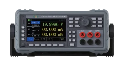
XGY power supply solutions span programmable DC sources, AC grid simulators, bidirectional supplies, regenerative AC/DC platforms, electronic loads, and power-line test interfaces for R&D, validation, compliance, and production benches.
View product
Product family
Battery Testers
XGY battery test configurations are scoped from the cell, module, pack, or DC-bus workflow. The system may combine bidirectional DC supplies, regenerative source/sink equipment, electronic loads, safety hardware, software recipes, and report output for EV, energy-storage, charger, and power-electronics validation.
View product
Product family
Electronic Loads
XGY programmable DC electronic loads run from the compact benchtop N621 to the modular N692, which covers 150 V to 2400 V classes and currents up to 2500 A. Both run CC, CV, CR, CP, dynamic, discharge, sequence, short-circuit, and protection-test modes for power supply, battery, charger, converter, and fuel-cell work.
View productFAQ
Frequently asked questions
What fields are mandatory in a battery test system RFQ?
Include voltage, current, source/sink power, channel count, duty cycle, regeneration, cooling, battery interface, BMS communication, safety states, report fields, destination, end use, and acceptance evidence.
What acceptance checks should be required?
Require a known-good run, a forced-fail state, an emergency-stop or interlock check, a report sample, software version record, channel map, and any calibration or verification references that apply.
When is a regenerative system needed?
Regeneration should be reviewed when discharge energy, duty cycle, heat load, or operating cost would make a purely dissipative load unsuitable. The quote should define grid return, utility needs, and thermal behavior.
Can battery test systems be exported from Australia?
Yes where the project and compliance review support it. Destination, end user, end use, and technical scope should be reviewed before order release, not after the system is built.
Keep exploring
Related technical resources
Related articles
Technical Article
Bidirectional DC Power Supply Selection for Battery Cycling
How to evaluate bidirectional DC power supplies for battery cycling, inverter validation, regenerative load testing, and EV bench workflows.
Read article
Technical Article
Regenerative AC/DC Source Planning for EV and Power Electronics Test
A planning guide for regenerative AC/DC sources used in EV chargers, inverters, grid simulation, and power electronics validation.
Read article
Technical Article
Automated Test Rack Acceptance Plan for Australian-Made Systems
How to define acceptance criteria for Australian-made automated test racks, including measurements, safety, reports, FAT/SAT evidence, and export review.
Read article