
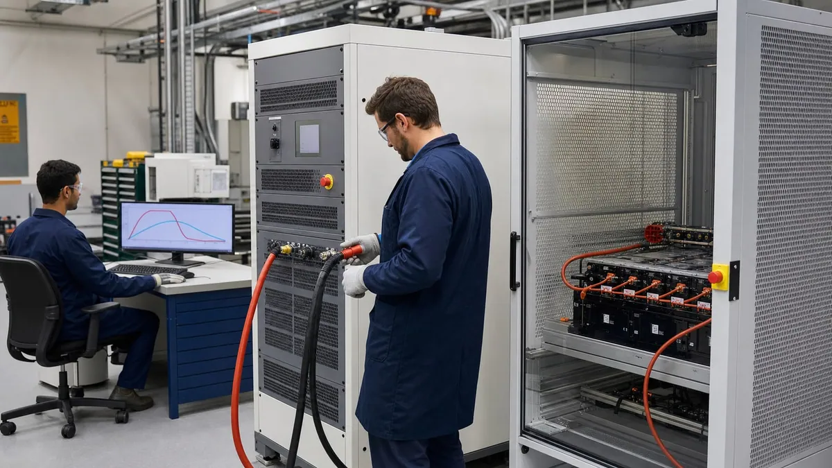
In brief
Choose a bidirectional DC supply from the complete source-and-sink profile—not headline ratings—then verify regenerative behavior, facility compatibility, protection, control software, and fault recovery with acceptance evidence.
Key takeaways
- Map minimum and maximum voltage, continuous and peak current, continuous and pulse power, profile duration, and thermal conditions across the full cycle.
- Verify continuous sink capability, source-to-sink transitions, regenerative behavior, cooling, and facility constraints as carefully as source ratings.
- Acceptance should exercise a normal cycle, a forced electrical limit, a safety input, communication loss, a sink event, and a reviewed report export.
- Treat the supply as part of an energy-handling and safety system rather than as a standalone instrument.
A bidirectional DC source is not simply a conventional supply with a negative-current setting. It is an energy-transfer element that must control two directions, remain stable with a changing electrochemical or power-electronic load, coordinate protection, and place returned energy somewhere safe. Selection therefore starts with the test method and system boundary, not the maximum voltage printed on a product page.
Use one documented sign convention throughout requirements, software, and reports. In this article, positive current means the source delivers energy to the DUT; negative current means the DUT returns energy to the source. Instantaneous DC power is P = V x I. Positive power is source operation and negative power is sink operation under that convention. A different convention is acceptable, but mixing conventions across the BMS, supply, and report can reverse a protection decision.
Convert the recipe into a two-direction operating map
List every charge, discharge, rest, pulse, pre-charge, and abort segment as an operating point or bounded trajectory. For each segment include voltage range, current limit, power limit, duration, repetition, ramp, settling requirement, and permitted temperature. The continuous operating area is more important than isolated maxima because the supply can be current-limited at one voltage and power-limited at another.
The selection worksheet should distinguish:
- maximum terminal voltage from normal working voltage and minimum controlled voltage;
- continuous source current from peak source current and its permitted duration;
- continuous sink current from peak sink current and its permitted duration;
- continuous source and sink power, including any voltage-dependent derating;
- transition direction, slew, overshoot, settling window, and allowed dead time;
- energy per cycle and cumulative energy over the planned unattended run;
- remote-sense point, cable drop, connector resistance, and contactor/pre-charge topology;
- ambient and coolant conditions, chamber interaction, altitude if relevant, and rack airflow;
- local and remote control ownership, command timeout, trigger, data rate, and clock requirements.
Do not assume source and sink ratings are symmetrical. Do not assume a pulse rating is repeatable without a duty-cycle limit. Do not assume parallel operation preserves transient behaviour, current sharing, isolation, or fault containment. Each of those is a requirement to verify against approved product data and then demonstrate in the integrated bench.
Treat energy and stored energy separately
For sampled voltage and current, transferred energy can be estimated by E = sum(V_k x I_k x delta_t_k). Separate positive and negative totals rather than reporting only their algebraic sum; otherwise a large charge and discharge cycle can appear to have little activity. Regenerated facility energy is not identical to DC energy absorbed from the DUT. Conversion loss, auxiliaries, cooling, standby consumption, and facility conditions affect the net result.
The DUT and bench also store energy outside the battery. A DC-link capacitor contains E_C = 0.5 x C x V^2; an inductor contains E_L = 0.5 x L x I^2. These equations are useful for identifying why a stop command does not instantly create a de-energised state. They are not by themselves a safety calculation: component tolerance, distributed capacitance/inductance, converter behaviour, discharge resistance, contactor state, and fault paths must be included in the project analysis.
Ask where energy goes in four cases: normal discharge, commanded abort, emergency stop, and facility-power loss. A regenerative source may return energy during normal operation but be unable to do so after its grid interface trips. The bench may then need an alternate controlled discharge or containment strategy. “Regenerative” must not be interpreted as “can always absorb energy.”
Separate control, protection, and emergency functions
The recipe controller manages intended operation. Instrument limits constrain commands. Independent protective functions address hazards identified by risk assessment. Emergency functions bring the system to a defined safe state. These layers may exchange status, but a software recipe should not silently become the only protective layer for a high-consequence fault.
Specify responses to over-voltage, over-current, over-power, over-temperature, reverse polarity, remote-sense failure, communications loss, BMS heartbeat loss, contactor disagreement, insulation-monitor trip, cooling loss, guard opening, and emergency stop. For every event, define current command, converter state, contactor action, discharge path, terminal-voltage verification, alarm retention, and reset authority.
Transition behaviour deserves its own acceptance case. A battery or inverter can force current while the source crosses through zero. The RFQ should state allowable voltage deviation, current overshoot, transition time, and whether the test tolerates a dead band. Never copy a catalogue transition number into a system guarantee without the stated load, voltage, wiring, control mode, and measurement conditions.
Match the standards to cell, pack, and equipment scope
IEC 62660-1 addresses performance and life testing of lithium-ion propulsion cells, while IEC 62660-3 addresses their safety performance. ISO 12405-4 applies to traction battery packs and systems for performance testing. These sources support a disciplined distinction between cell-level and pack/system-level work; they do not make one generic cycling recipe universally valid.
IEC 62477-1 provides safety context for power electronic converter systems, expressly including bidirectional power converters within its broader scope. IEC 61010-1 provides general safety context for test, measurement, control, and laboratory equipment. A project may have other product, machinery, vehicle, installation, grid, or workplace requirements. The applicable set must be established by the responsible engineering and compliance process.
An accredited result is also different from an instrument capability. ISO/IEC 17025 concerns laboratory competence, impartiality, and consistent operation. Buying a calibrated bidirectional source does not make a test accredited. Method control, personnel competence, traceability, environment, uncertainty, records, and the laboratory’s accredited scope still matter.
Measurement uncertainty and decision integrity
Near a current, energy, efficiency, or capacity threshold, the bench must quantify enough uncertainty to prevent the display resolution from being mistaken for knowledge. Potential contributors include voltage and current calibration, offset, gain drift, temperature, range changes, transducer phase delay, sampling timebase, channel skew, cable drop, sense-point location, numerical integration, DUT stabilisation, and test-to-test repeatability.
For a steady DC power point with independent relative standard uncertainties, a first-pass model is u_r(P) = sqrt(u_r(V)^2 + u_r(I)^2). Dynamic profiles need more: timing and channel alignment can dominate, and correlated terms should not be combined as if independent. NIST Technical Note 1297 is the primary-source basis for identifying components and reporting combined or expanded uncertainty. The final budget must follow the actual measurement model.
Write the decision rule before running acceptance. If a maximum current is safety-critical, the rule may require measured value plus a defined guard band to remain below the limit. If a performance result is close enough that uncertainty could change the verdict, “inconclusive” and corrective investigation can be more defensible than an automatic pass.
Selection and acceptance matrix
| Engineering decision | Required input | Acceptance evidence | Reject or hold when |
|---|---|---|---|
| Source operating area | All (V, I) charge points, continuous/pulse power, duration, and thermal condition | Recorded profile at low-, nominal-, and high-voltage boundaries | Only maximum voltage/current are compared, or a required point falls in derating |
| Sink operating area | Discharge points, returned energy, transition direction, and facility state | Continuous sink run, source-to-sink transition, and facility-facing status | Sink is treated as a brief electronic-load feature with no continuous or site evidence |
| Dynamics | Slew, overshoot, settling, dead band, sense point, and DUT impedance range | Captured transition under a representative safe load and wiring configuration | A catalogue timing value is used without system measurement conditions |
| Safety state | Fault list, protective layers, contactor/discharge logic, time-to-safe, and reset authority | Forced electrical limit, communications loss, interlock, emergency stop, and safe-voltage verification | The rack relies on a normal software stop for every hazardous event |
| Data quality | Measurands, sample timing, correction, uncertainty, raw retention, and report fields | Raw-to-report reconciliation with instrument/configuration versions | Energy or capacity verdict cannot be reconstructed or its uncertainty is unknown |
| Throughput | Recipe duration, loading, thermal recovery, channel concurrency, and retest rule | End-to-end cycle-time run including reporting and controlled recovery | “Fast switching” is assumed to equal production takt time |
Illustrative worked example — not a customer case
Consider a fictional battery module that operates from 250 V to 450 V. Its method requests 80 A charge, 100 A discharge, 30 kW continuous power in either direction, and a 40 kW discharge pulse for 10 seconds once every five minutes. At 250 V and 100 A, the discharge point is 25 kW. At 450 V and 80 A, the charge point is 36 kW, so the 30 kW continuous power limit—not the 80 A current limit—would control that step unless the recipe lowers current to about 66.7 A (30,000 / 450).
This simple calculation exposes a requirements conflict before equipment selection. The buyer must decide whether 80 A at 450 V is genuinely required continuously, required only as a time-qualified pulse, or not a valid operating combination. A supplier cannot resolve that ambiguity by choosing a higher headline current alone.
If the fictional DUT returns 30 kW for 30 minutes, 15 kWh reaches the source-side DC interface under an ideal constant-power assumption. The facility does not necessarily receive 15 kWh. Net returned energy depends on converter efficiency at that point, auxiliary loads, cooling, transitions, and whether site conditions permit grid return. The RFQ therefore asks for both DUT-side energy handling and facility-side behaviour, without promising a savings figure.
Acceptance for this example would capture the 250 V/100 A sink point, the 450 V power-limited source point, a 40 kW time-qualified pulse if supported by the selected configuration, a controlled source-to-sink transition, a communications timeout, and a verified safe discharge after abort. The numbers are pedagogical inputs, not XGY ratings or a customer result.
Product-family boundary
Within the current approved XGY product content, N351 is the lower-voltage, compact starting point: listed 2.5 kW, 5 kW, and 7.5 kW models; 40 V or 80 V ranges; bidirectional source/load operation; listed regeneration up to 90%; and LAN, RS232, RS485, and CAN interfaces with the stated protocol options. Those values must remain attached to the specific model and approved operating conditions. They are not a guarantee that every battery profile or facility can use regeneration.
N355 is the higher-voltage and higher-power starting point: model-dependent voltage coverage listed up to 2250 V, listings up to 42 kW in 3U, regeneration listed up to 93%, a stated voltage rise/fall boundary of no more than 5 ms under its specified conditions, and supported parallel expansion. At this class, contactor coordination, insulation, cable/terminal access, fault energy, facility return, and site commissioning become system decisions. The article does not extend any one model’s ratings across the family.
For buyers searching for a high-capacity bidirectional DC power supply, translate “capacity” into a verified voltage-current operating area, continuous source and sink power, time-qualified pulse limits, profile duration, and thermal conditions. The N355 family is the higher-power XGY starting point, but the selected model and configuration still have to cover every operating point and the facility-side energy path.
Maintain the complete bidirectional power path
Bidirectional power-flow maintenance covers more than periodic supply calibration. The maintenance plan should inspect high-current connectors and contactors, cooling paths and filters, remote-sense wiring, insulation and grounding, emergency-stop and controlled-discharge behaviour, and the regenerative facility interface. Retain fault and energy logs, verify safe recovery after a forced interruption, and repeat acceptance checks after cabling, firmware, protection, or facility changes. The interval and procedure must follow the approved equipment documentation and the site risk assessment.
Common failure modes
- A source is chosen from maximum voltage while the low-voltage/high-current point is outside its operating area.
- Sink power is available only briefly, but the method requires continuous discharge.
- Regeneration is specified without a facility review or a non-regenerative fault strategy.
- Remote sense corrects cable drop in normal operation, but open-sense behaviour is untested.
- A fast front-panel transition is assumed to remain fast through long cables, contactors, filters, and DUT controls.
- Charge and discharge energy are netted, hiding directional error or lost samples.
- A pass report retains results but not recipe revision, source settings, raw data, or uncertainty.
Source-to-claim map
| Claim area | Primary-source basis | Boundary retained |
|---|---|---|
| Cell performance, life, and safety methods are distinct | IEC 62660-1 and IEC 62660-3 | Exact test profiles and acceptance criteria must come from the applicable programme and purchased standard |
| Pack/system performance is not the same as cell testing | ISO 12405-4 | Applicability to a specific vehicle programme is not assumed |
| Bidirectional converters require system safety consideration | IEC 62477-1 and IEC 61010-1 | No certification claim is made for the integrated bench |
| Measurement claims need uncertainty and controlled reporting | NIST TN 1297 and ISO/IEC 17025 | A simplified power model does not replace a method-specific budget or accredited scope |
Product fit
Where XGY Tek fits
The N351 and N355 bidirectional DC supply families can be reviewed for battery-cycling and regenerative power benches after the complete voltage, current, power, sink, facility, control, and safety envelope is known. Model selection remains subject to the verified DUT profile and installation conditions.
Power Supplies
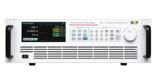
N351 Bidirectional Programmable DC Power Supply
XGY N351 is a bidirectional programmable DC power supply for tests that need current to flow both from the supply to the DUT and from the DUT back to the grid. Regenerative operation can reduce heat dissipation and improve test-system efficiency.
View product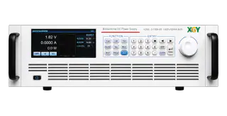
Power Supplies
N355 High Power Bidirectional Programmable DC Power Supply
XGY N355 is a bidirectional programmable DC power supply for high-power test scenarios that need source and sink capability in one programmable DC platform. With up to 42 kW of power in a 3U chassis and master/master parallel capability to MW-level systems, it supports both lab validation and production-line ATE.
View productFAQ
Frequently asked questions
How do you size a bidirectional DC supply for battery cycling?
Size it from the complete charge and discharge profile: minimum and maximum battery voltage, continuous current, peak current, continuous power, pulse power, rest time, sink duration, and expected thermal conditions. A single maximum-voltage number is not enough because many battery tests are limited by current at low voltage or by power at high voltage.
What is the difference between electronic-load operation and regenerative operation?
Electronic-load operation absorbs DUT energy and typically turns it into heat inside the load or cooling system. Regenerative operation can return absorbed energy to the facility side when the installation supports it. The regenerative path still needs site review for protection, grounding, emergency stop behavior, and grid compatibility.
When should the N351 class be considered instead of the N355 class?
The N351 class fits compact, lower-voltage regenerative benches such as module-level cycling, DC bus exercises, and production stations around 40 V or 80 V ranges. The N355 class belongs in higher-voltage or higher-power validation where the review must include insulation, contactors, facility regeneration, commissioning tests, and fault energy.
What should acceptance prove before a battery bench is released?
Acceptance should prove source mode, sink mode, transition behavior, recipe limits, emergency stop response, communication-fault response, data logging, and safe recovery after an abort. A useful test includes a normal cycle, a forced limit, and a documented fault case rather than only a successful steady-state run.
Keep exploring
Related technical resources
Related articles
Procurement Checklist
Battery Test System Quote Requirements for Engineering Buyers
What to include in a battery test system quote request, including voltage, current, regenerative operation, safety states, reporting, and acceptance evidence.
Read article
Technical Article
Regenerative AC/DC Source Planning for EV and Power Electronics Test
A planning guide for regenerative AC/DC sources used in EV chargers, inverters, grid simulation, and power electronics validation.
Read article
Technical Article
Automated Test Rack Acceptance Plan for Australian-Made Systems
How to define acceptance criteria for Australian-made automated test racks, including measurements, safety, reports, FAT/SAT evidence, and export review.
Read article