
In brief
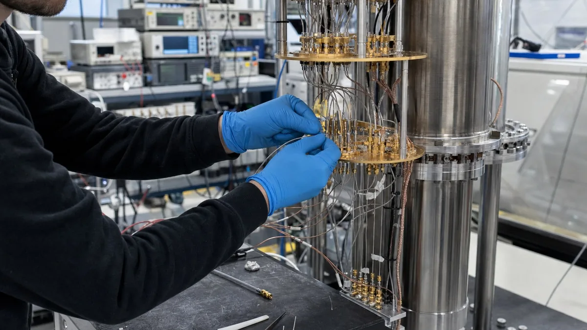
Select cryogenic quantum interconnects against the complete RF and thermal path, including signal role, loss and attenuation, cold-stage heat load, connectors, routing, repeatability, and documentation; frequency range alone is insufficient.
Key takeaways
- Map the complete signal path, target refrigerator stage, expected device-level signal, and the role of each interconnect before selecting cable construction.
- Balance insertion loss and attenuation against cold-stage heat load and the available thermal budget.
- Specify connectors, stage-to-stage routing, bend radius, anchoring, labeling, and phase or amplitude repeatability requirements before quotation.
- Accept an interconnect only when its RF evidence, thermal plan, mechanical installation details, and configuration record match the experiment.
Cryogenic quantum interconnect selection is a coupled RF, thermal, mechanical, and metrology problem. A cable may pass a room-temperature S-parameter check and still be unsuitable because it conducts too much heat to a cold stage, thermalizes poorly, shifts the effective reference plane after cooldown, or cannot be routed without loading a connector. The defensible unit of selection is therefore the complete line from the room-temperature instrument to the device package, not the cable part number in isolation.
Classify every line by function
Begin with a line register. For each path, record whether it is a microwave drive, readout output, flux or fast-bias line, low-frequency bias, clock/reference, amplifier bias, sensor, or spare. Then record the source and receiver impedance, frequency or edge-rate content, maximum stimulus, expected device-level signal, direction of power flow, target refrigerator stage, duty cycle, permitted noise, and required service access.
Line role changes the design. A drive path often needs deliberate attenuation and thermalization of incoming noise. A readout path often prioritizes low loss between the device and the first cryogenic amplifier while maintaining isolation from amplifier back-action. A DC bias path may be governed by filtering, conductor count, leakage, magnetic compatibility, and heat conduction rather than microwave insertion loss. Applying one cable construction and one attenuation pattern to all three roles is not an engineering shortcut; it hides different failure mechanisms.
The line register should also show every discontinuity: bulkhead, feedthrough, adapter, attenuator, filter, isolator, circulator, amplifier, connector pair, and sample launch. This is the configuration that must be modelled and later reconstructed.
Build the conductive heat-load model
For a uniform element of length L and cross-sectional area A, a first-order steady-state conductive heat flow between temperatures T_c and T_h is:
Q_dot = (A / L) * integral from T_c to T_h of k(T) dT
where k(T) is the temperature-dependent thermal conductivity. A coaxial line is composite, so calculate the centre conductor, outer conductor, dielectric, armour, and any parallel metallic path separately, then sum them. A room-temperature conductivity value is not an adequate substitute for the integral. NIST’s cryogenic materials references and the primary dilution-refrigerator study cited below support using temperature-dependent data.
This calculation is an estimate, not proof of installed heat load. It assumes geometry, material state, and thermal boundary conditions are known. Connector bodies, solder joints, imperfect anchor contact, plating, braid, support hardware, and harness-to-harness conduction can change the result. Assign the estimated load to each receiving stage, add the active dissipation discussed below, and compare the total with the refrigerator’s available cooling power at the intended operating temperature, not a headline base temperature with no load.
Treat attenuation as both noise conditioning and heat
Thermal radiation in a microwave mode cannot be represented adequately by kT at every cryogenic frequency. The mean Bose-Einstein photon occupation is:
n_BE(f,T) = 1 / (exp(h*f/(k_B*T)) - 1)
For a matched attenuator with linear power loss L_a >= 1, ideally thermalized at temperature T_a, a useful line model is:
n_out = n_in / L_a + (1 - 1/L_a) * n_BE(f,T_a)
This shows why nominal attenuation alone is insufficient. The attenuator suppresses incoming noise but also emits noise associated with its own physical temperature. Poor mechanical contact can make its effective temperature different from the plate thermometer. The same attenuator dissipates signal power: for incident power P_in, the ideal matched dissipation is P_in * (1 - 1/L_a). Include duty cycle, pulses, mismatch, and cable loss when moving beyond this screening equation.
Create a stage-by-stage table containing passive conduction, attenuator dissipation, cable dissipation, amplifier or bias dissipation, and margin. Do not move attenuation to a colder stage merely to improve the photon calculation without checking whether that stage can absorb the active load.
Define the RF reference plane and evidence
Room-temperature S-parameters are useful incoming evidence, but they do not automatically describe the cold installed line. Cable loss, connector reflection, component response, and physical length can change with temperature. The primary cryogenic calibration paper cited below demonstrates why an attenuator, cable, and sample package should be treated as a cascade and why the reference plane must be stated.
For each requested Touchstone file, record cable ID, connector orientation, frequency grid, source power, IF bandwidth, calibration method, calibration plane, connector inspection and torque practice, ambient or cryogenic condition, and measurement date. If the file is only a room-temperature acceptance check, say so. If it will be used to correct device data, the uncertainty and validity of that use require a stronger calibration and verification plan.
Matching several channels requires a definition. “Phase matched” might mean equal phase at one frequency, maximum phase difference over a band, matched group delay, or repeatability after a cooldown. These are not interchangeable. State the metric, band, routing state, temperature state, and whether the acceptance limit applies to initial matching or post-cycle change.
Mechanical, vacuum, and magnetic boundaries
Cable length should be defined stage to stage, including service loops and the portion consumed by bends. Record minimum bend radius, connector exit direction, pre-forming, plate penetration, clamp width, anchor material, strain relief, loom spacing, and the assembly sequence. A cable that requires connector side-load to reach an anchor should fail the design review before cooldown.
Vacuum compatibility is a material and process question, not a generic statement about a cable family. Review jackets, adhesives, heat-shrink, labels, lubricants, cleaning residues, solder or braze processes, and trapped volumes against the facility’s vacuum procedure. Similarly, “non-magnetic” needs an agreed measurement method, field or susceptibility criterion, component scope, and temperature context. Do not convert a connector material description into a guaranteed experiment-level magnetic-field result.
Decision and acceptance matrix
| Decision gate | Required evidence | Release blocker |
|---|---|---|
| Line role | Controlled block diagram, line register, source/receiver levels, band, duty cycle, and target stage | Frequency range is known but signal role, stage, or level is not |
| Thermal budget | Temperature-dependent conduction model, active dissipation by stage, cooling-power basis, and margin | A cold-stage load is omitted or based only on room-temperature conductivity |
| Noise plan | Attenuation and filtering by stage, physical-temperature assumption, and photon/noise calculation | Nominal dB is treated as proof of thermalization |
| RF integrity | Calibration plane, S-parameter conditions, connector practice, cascade model, and verification device | A file has no cable identity, condition, or reference plane |
| Installation | Routing drawing, bend and anchor details, feedthrough map, labels, strain relief, and assembly order | Installation needs unplanned adapters, unsupported weight, or connector side-load |
| Reproducibility | As-built line map, serial/lot data, photos, configuration files, deviations, and post-service check | The path cannot be reconstructed after warm-up or service |
Failure modes worth challenging
- A low-loss conductor meets the RF budget but consumes unacceptable cold-stage cooling margin.
- An attenuator is electrically correct but thermally anchored through a high-resistance interface, so its effective temperature is unknown.
- A room-temperature calibration is silently used as a cryogenic correction without evidence that the model remains valid.
- Parallel lines are labelled at the room-temperature flange but not at intermediate plates, creating mapping errors after service.
- A service loop violates bend or clearance constraints during shield installation.
- A connector described as non-magnetic is combined with unreviewed fasteners, solder, or nearby hardware.
- A phase-matched set is accepted at one frequency even though the experiment depends on group delay across a band.
Illustrative worked example - not a customer case
Assume a hypothetical 6 GHz drive line includes a 20 dB attenuator at one stage. A 20 dB power attenuation corresponds to L_a = 100. If the incident continuous-wave power at that attenuator were -60 dBm, or 1 nW, the ideal matched dissipation would be 1 nW * (1 - 1/100) = 0.99 nW. That arithmetic does not establish the actual stage load: real duty cycle, upstream loss, reflection, pulse envelope, attenuator temperature, and thermal contact still have to be measured or bounded.
The engineering team then finds that the proposed cable has adequate room-temperature S21, but its conductive model uses only a 300 K material value. Release is withheld. The team replaces that estimate with temperature-dependent integrals for each cable constituent, adds connector and anchor assumptions, assigns the loads stage by stage, and records a verification measurement after installation. The lesson is procedural: a correct RF trace cannot substitute for a thermal model, and a thermal model cannot substitute for an RF acceptance record.
This is an invented teaching example. It is not an XGY Tek or customer project, not a measured performance result, and not a recommendation that every 6 GHz line use 20 dB at the described stage.
Source-to-claim map
| Engineering statement in this article | Primary or official basis |
|---|---|
| Coaxial wiring density creates a cryogenic heat-load problem | NIST Cryogenic Photonic Interconnects |
| Passive conduction, active dissipation, and thermal-noise conditioning must be evaluated together | Krinner et al., EPJ Quantum Technology |
| Attenuator temperature and drive-line thermal noise are system properties | PRX Quantum primary experiment |
| Cold reference-plane calibration and cascaded package elements matter | Review of Scientific Instruments primary paper |
| Conductive models require temperature-dependent material properties | NIST cryogenic materials reference list |
k_B*T and thermodynamic temperature use the SI kelvin definition | BIPM SI kelvin page |
| Uncertainty contributions must be identified and reported for decision use | JCGM GUM publications |
XGY product-data boundary
The related XGY product page lists cryogenic cable assemblies, high-density assemblies, hermetic flange or adapter options, multi-pin feedthroughs, and SMA or 2.92 mm K connector options. Those statements define a portfolio review boundary only. They do not establish a universal temperature range, heat leak, insertion loss, phase match, vacuum performance, magnetic-field limit, cooldown life, or experiment compatibility. Final configuration requires the line register, thermal and RF budgets, material/process review, routing drawing, and acceptance evidence described above.
Product fit
Where XGY Tek fits
XGY Tek's cryogenic interconnect range can be reviewed for dilution-refrigerator wiring, microwave signal paths, and low-temperature measurement setups when the RF budget, thermal load, mechanical routing, and documentation requirements are defined. Final configuration remains experiment-specific.
FAQ
Frequently asked questions
What makes a cryogenic RF cable different from a normal microwave cable?
A cryogenic RF cable has to satisfy the RF path and the thermal path at the same time. Frequency range, insertion loss, return loss, connector repeatability, and phase stability still matter, but the line must also be compatible with stage anchoring, heat load, bend radius, cooldown cycles, and limited access inside the refrigerator.
When should a lab request measured S-parameters?
Measured S-parameters are worth requesting when the line sits in a calibration-sensitive control, readout, or reference path. The request should state frequency span, connector condition, torque practice, room-temperature or cryogenic measurement condition, and whether the file is for incoming inspection, model correlation, or experiment documentation.
How should attenuation be specified for a quantum control line?
Attenuation should be specified by its role in the signal chain, not only by a single cable-loss number. The lab should define source level, attenuators, filters, cold-stage location, expected level at the device, acceptable heat load, and whether attenuation is intentional for noise and thermalization control.
What information prevents installation problems?
Stage-to-stage length, connector type and orientation, minimum bend radius, anchor points, feedthrough style, cable grouping, label format, and installation notes prevent most mechanical surprises. A cable that is electrically suitable can still fail the project if it cannot be routed or serviced safely.
Keep exploring
Related technical resources
Related articles
Technical Article
Phase-Stable RF Test Cable Buying Guide
How to evaluate phase-stable RF test cables for VNA measurement, production test, field use, and mmWave benches.
Read article
Technical Article
THz and mmWave Module Selection for Signal Chains
A selection guide for THz and mmWave modules, active waveguide modules, W-band multipliers, and passive waveguide components.
Read article
Technical Article
RF Signal Generator Checklist for Receiver Test
How to select an RF signal generator for receiver sensitivity, radar, 5G, satellite, and automated RF test workflows.
Read article