
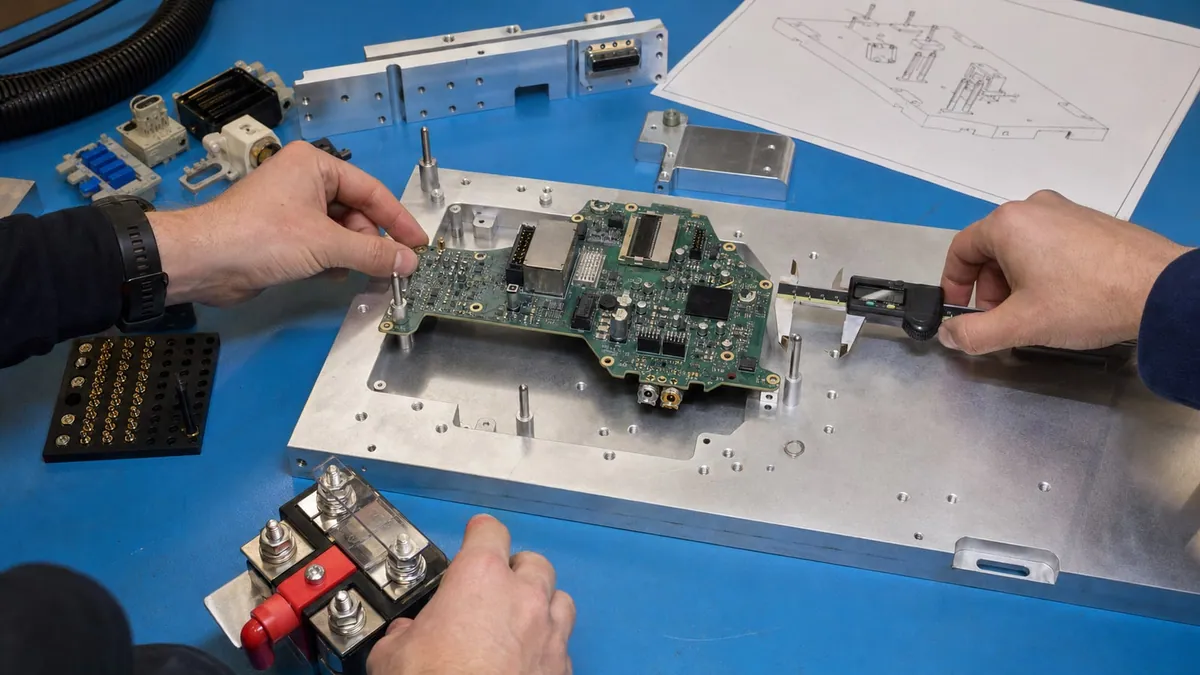
In brief
A custom test fixture can be quoted defensibly only when the DUT geometry, contact map, measurement path, operator workflow, safety states, software interfaces, lifetime target, and acceptance evidence are defined before design release.
Key takeaways
- Provide controlled DUT drawings, contact locations, keep-outs, tolerances, alignment needs, and surfaces that cannot be marked or loaded.
- Define the electrical or RF path, calibration plane, voltage/current limits, shielding, cable movement, and safe-state behavior alongside the mechanical design.
- Scope loading sequence, product variants, cycle-life target, maintenance access, software hooks, and report requirements before machining starts.
- Acceptance should cover repeated loading, path verification, a known-good and known-fail case, a safety input, operator error handling, and report export.
Custom test fixtures are easiest to quote when the mechanical, electrical, and workflow constraints are known before the first drawing is released. A fixture is not only a holder for the device under test. It defines how the operator loads the DUT, how contacts are made, how measurement paths are protected, how safety states are enforced, and how repeatability is preserved after hundreds or thousands of cycles.
Start with the DUT and contact map
The first scoping package should include the DUT outline drawing, 3D model if available, connector locations, keep-out zones, pad pitch, board thickness, expected tolerances, and any surfaces that cannot be scratched or loaded. If the fixture touches spring-pin pads, coaxial launches, high-current terminals, optical ports, or fragile semiconductor packages, each contact needs a clear purpose and a target lifetime.
For board-level fixtures, identify whether the fixture contacts pads, connectors, test points, edge fingers, pogo pins, coaxial ports, or a combination of these. For semiconductor and RF fixtures, define the required alignment precision, probe type, shielding needs, calibration reference, and whether the DUT must remain visible under a microscope or camera.
Define the measurement path
The electrical and RF path should be scoped with the same care as the mechanical clamp. RF fixtures should state the frequency range, connector type, cable length, required shielding, calibration plane, allowed cable movement, and whether repeatable phase or insertion loss is important. A fixture that is fine at low frequency can become the main uncertainty source at microwave or mmWave frequencies if launch geometry, cable strain, or shielding is not controlled.
Power fixtures need voltage, current, peak power, insulation requirements, thermal limits, safe-discharge behavior, and interlock expectations. If the DUT can store energy, the fixture should define what happens after a failed test, emergency stop, door opening, or communication loss. For high-current contacts, also define allowable temperature rise, contact replacement method, and how operators will recognize wear.
Scope the operator workflow
Production fixtures should be designed around the operator’s real sequence: scan barcode, load DUT, close fixture, confirm seating, run test, display pass/fail, unlock, remove DUT, and store records. The quotation request should state target loading time, expected daily volume, shift pattern, cycle count, access for cleaning, and spare-part strategy. If the station must support several product variants, include recipe selection rules and any interchangeable nests, adapters, or keyed inserts.
This is where many fixture projects drift. The mechanical design may look finished, but the operator workflow may still be unclear. If serial-number capture, label printing, MES upload, or exception handling is required, those items should be scoped before the fixture is machined.
Add safety and acceptance criteria
A fixture used in RF, high voltage, high current, or automated motion should have explicit safety states. Define guard doors, presence sensors, emergency stop response, discharge delay, grounding points, shield connection, and who can reset a fault. If the fixture integrates into an automated test system, document the software hooks: open/closed state, DUT present, fixture locked, interlock healthy, test running, and safe to unload.
Acceptance should include more than one successful measurement. A useful fixture acceptance plan includes repeated load/unload cycles, contact resistance checks where relevant, RF path verification or calibration data, safety-state tests, operator prompts, report output, and replacement-part documentation. For critical fixtures, include a known-good DUT and a known-fail case so the station proves both pass and fail behavior.
Fixture acceptance matrix
A custom fixture should be accepted as a measurement interface, not as a finished machined part. The evidence must show that the DUT is seated consistently, contacts are controlled, the measurement path is stable, and unsafe states are blocked.
| Acceptance item | Evidence to capture | Reject or rework if |
|---|---|---|
| DUT seating and contact map | DUT drawing revision, nest drawing, contact list, keep-out review, seating check, and repeated load/unload result | Contacts land near pad edges, seating depends on operator feel, or the fixture cannot tolerate DUT drawing variation |
| Electrical/RF path verification | Contact resistance, insulation, RF insertion/return loss, calibration plane, shielding check, and cable strain review | The fixture passes one measurement but changes when the lid closes, cable moves, or the DUT is reloaded |
| Safety-state behavior | Door/lock sensors, emergency stop, discharge delay, high-voltage or high-current interlocks, and reset authority | The station can start before lock confirmation, or a failed test leaves stored energy without a defined safe state |
| Operator workflow | Barcode or ID capture, prompts, pass/fail display, unload permission, exception flow, and target cycle time | Operators can skip required steps, select the wrong recipe, or unload before the system is safe |
| Maintainability | Contact replacement method, spare parts, cleaning access, wear indicators, service interval, and documentation package | Wear items are hidden, replacement changes alignment, or the station has no path-health check after service |
Fixture failure modes to challenge
The fixture review should deliberately look for the failures that do not appear in a clean CAD render: side-loaded coax connectors, spring pins outside their working travel, inconsistent DUT seating, cable strain during clamp closure, shield leakage after repeated opening, high-current heating at contact points, and software that starts a test before the fixture is locked. These are not cosmetic concerns; they become measurement drift, operator frustration, and false pass/fail decisions.
Quantify the fixture where the risk lives. A scoping package should name the measurement bandwidth in Hz, MHz, or GHz; voltage and current limits in V and A; target cycle life in cycles; expected daily DUT count; contact replacement interval; and any report-retention requirement in days or months. For RF fixtures, add connector family, calibration plane, shielded-enclosure requirement, cable bend radius in mm, and a before/after load-unload comparison. For power fixtures, add discharge delay in seconds, interlock state count, maximum stored energy if known, and the reset authority after a fault.
Use example values only to force the review to become concrete: a 40 GHz RF fixture should identify the connector family and calibration plane; a 60 V / 10 A power fixture should document contact heating and insulation; a production nest targeting 5000 cycles should state the cleaning and contact-replacement trigger; a fixture with a 5-second discharge delay should prove the safe-unload state; and a report-driven station should preserve at least 10 fields that tie the result to DUT ID, fixture revision, operator, limits, instrument IDs, and software version. Replace those example numbers with the actual project limits before quotation.
For XGY test fixtures, the product-line boundary is broad enough to include spring-pin nests, coaxial launches, RF shielded enclosures, high-voltage interlocks, sensors, barcode workflow, and automation hooks. The quotation should therefore state which risks the fixture itself must control and which risks belong to the rack, software, or operator procedure. That split is what lets the fixture become a repeatable measurement interface rather than a custom mechanical part with unclear responsibility.
Reject a fixture acceptance result when it proves only the happy path. A credible handover includes repeated loading, one known-good DUT, one known-fail or forced-limit case, one safety input, one operator error path, and one report export. If the fixture cannot show those cases, the project is still in prototype territory.
Engineering decision method before quotation
Use a risk-led sequence rather than beginning with CAD. First freeze the measurement intent: measurand, stimulus, range, limit, required resolution, environmental state, and reference plane. Second define the physical interface: controlled DUT revision, datum scheme, tolerance stack, contact type, working travel, force or torque constraint, keep-outs, and permitted marking. Third allocate every function to the fixture, rack, software, or operator. Finally choose a verification method and objective evidence for each release-blocking requirement.
The allocation step prevents duplicated or missing controls. If both the fixture PLC and the test application believe they own the door interlock, recovery behaviour can become ambiguous. If neither owns cable-path verification, RF drift will be blamed on the instrument. Record one accountable owner and one authoritative state source for each critical function.
Before a fixed-price quote, label unresolved inputs. A missing final DUT drawing, unknown connector mating limit, unsettled thermal state, or undefined production rate is not a minor assumption; it changes contact selection, actuation, service access, validation effort, and spares. The commercial proposal should either make the assumption explicit or quote a paid discovery/prototype gate before production release.
Quantitative acceptance logic
Fixture acceptance needs both attribute checks and variable data. Attribute checks answer questions such as whether the wrong DUT can be loaded or whether the test is inhibited while the guard is open. Variable data measure contact resistance, leakage, insertion loss, alignment, temperature, cycle time, or another relevant quantity. For each variable, state the acceptance limit, sample conditions, number of independent reloads, and decision rule before collecting results.
A practical repeatability calculation is the range across controlled reloads: maximum result − minimum result. It is easy to audit, but it is not a complete uncertainty evaluation. If the fixture result supports a conformance decision, include relevant effects such as instrument uncertainty, reference-device uncertainty, contact variation, cable movement, temperature, and operator positioning. NIST guidance emphasises that traceability belongs to the result and its documented chain, not to an instrument in isolation; the JCGM GUM supplies the broader uncertainty framework.
Do not set a universal “three runs equals validated” rule. Three reloads are a useful engineering screen, while production release may require a larger, risk-based study across operators, DUT variants, contact replacements, and environmental states. Predetermine whether any single failure blocks release, whether rework triggers a complete rerun, and which conditions can be accepted with a documented deviation.
Evidence package and change control
The quotation should name the handover deliverables, not leave them to goodwill. Include controlled DUT and fixture drawings, contact and cable lists, calculation or simulation assumptions where used, risk review, wiring and I/O map, software interface, calibration/reference-plane method, assembly and adjustment instructions, wear-part list, inspection and cleaning procedure, acceptance protocol, raw results, photos that support but do not replace measurements, and a deviation register.
Also define a revalidation trigger list. Changes to the DUT datum, pad finish, contact type, coaxial cable, adapter stack, clamping force, probe alignment, firmware, limit table, thermal hardware, or interlock logic can invalidate part of the evidence. The change record should say which risks changed and which acceptance steps must be repeated. A fixture revision number in every report provides the link between a result and the physical interface that produced it.
Illustrative worked example — not a customer case
Assume a hypothetical benchtop fixture contacts a small board at eight spring-pin nodes and one coaxial port. Its intended measurement path is limited to 6 GHz, while two nodes carry up to 2 A during a short functional step. The release plan requires correct seating, a closed-guard input, continuity on all low-frequency nodes, an RF path check at three agreed frequencies, a forced-open contact, and five independent unload/reload cycles.
The first build passes continuity but the RF result shifts beyond the project limit when the lid closes. Inspection shows that the coaxial jumper is pulled sideways during the final 15 degrees of travel. The design is not accepted even though one open-lid measurement passed. The team changes strain relief, issues a new fixture revision, repeats all RF and loading checks, and records each result rather than reporting only the average. The final evidence links the DUT drawing revision, fixture revision, cable identity, connector inspection, instrument configuration, and software limit file.
This is an invented teaching example, not a real XGY Tek or customer project, not a performance claim, and not evidence that such a fixture has been tested. The values illustrate how to write acceptance logic; actual limits, run counts, safety controls, and standard selections must come from the verified application.
Product fit
Where XGY Tek fits
XGY Tek can scope a custom test fixture when the DUT geometry, contact map, measurement path, loading workflow, safety states, lifetime target, and acceptance evidence are defined. Fixture construction and performance remain dependent on the verified project limits and integration boundary.
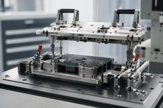
FAQ
Frequently asked questions
What drawings are needed before a custom fixture can be quoted accurately?
A useful package includes the DUT outline, connector or pad locations, keep-out zones, board thickness, tolerance stack, surfaces that cannot be marked, and the expected contact map. For RF, high-current, optical, or semiconductor devices, include the signal path and any alignment or force limits, not only the mechanical envelope.
How should fixture lifetime be specified?
Specify expected cycles per day, shift pattern, target service interval, contact replacement method, spare parts, and cleaning access. A fixture used for ten lab samples can be designed differently from one that must survive repeated production loading, barcode workflow, and operator variation.
What makes an RF fixture different from a low-frequency fixture?
An RF fixture must control launch geometry, shielding, cable movement, calibration plane, connector torque, and path repeatability. A mechanical clamp that holds the DUT securely can still be a poor RF fixture if the cable bends during closure or the calibration plane moves between calibration and measurement.
What should fixture acceptance include?
Acceptance should include repeated load/unload cycles, contact or path verification, safety-state checks, operator prompts, report output, and known-good or known-fail DUT behavior. One successful measurement is not enough to prove a fixture is ready for production use.
Keep exploring
Related technical resources
Related articles
Procurement Checklist
Semiconductor Test Fixture Validation Checklist
A semiconductor test fixture validation checklist covering probe access, SMU paths, RF cables, thermal conditions, repeatability, reports, and acceptance evidence.
Read article
Technical Article
Automated Test Rack Acceptance Plan for Australian-Made Systems
How to define acceptance criteria for Australian-made automated test racks, including measurements, safety, reports, FAT/SAT evidence, and export review.
Read article
Technical Article
Manual Probe Station Checklist for Wafer-Level Test
What to check before buying a manual probe station for semiconductor wafer, RF probe, and device characterization workflows.
Read article