
In brief
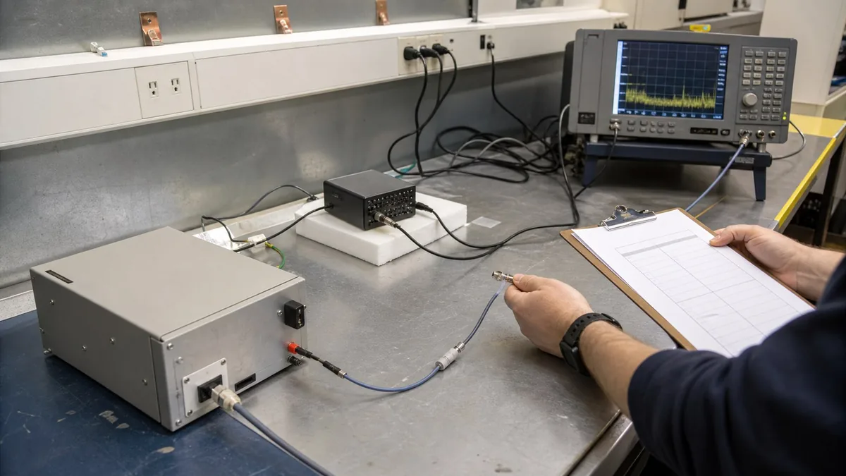
An EMC pre-compliance bench should be specified as a repeatable conducted-emissions workflow: match the LISN to the DUT power path, control cabling and grounding, record analyzer settings, and retain traceable reports. It supports engineering debug and comparison; it does not replace formal compliance testing.
Key takeaways
- Select the LISN from the DUT voltage, current, phase, grounding, termination, and receiver-protection requirements rather than current rating alone.
- Treat cable routing, DUT placement, grounding, operating mode, and analyzer settings as recorded test conditions so design revisions can be compared.
- Accept the bench only when another engineer can rebuild the setup, reproduce comparable data, and trace the result to raw exports and instrument records.
An EMC pre-compliance bench earns its value by making design comparisons earlier and more repeatable. It does not convert an engineering lab into a compliance laboratory, and it cannot turn an approximate setup into a certified pass. Its proper output is evidence: a controlled setup, a traceable measurement chain, a documented DUT mode, a defensible comparison, and a clear list of remaining risks before formal testing.
For conducted-emissions work, treat the system as five linked blocks: mains or DC source, LISN or other applicable coupling network, DUT and support equipment, RF path/protection, and measuring receiver or spectrum analyzer. A change in any block can change the result. The bench procedure should therefore control the entire chain rather than save only an analyzer screenshot.
Confirm the applicable method and limit first
The product category, port, power interface, intended market, and regulatory route determine the applicable emissions standard and limit. CISPR 16 publications provide apparatus, method, and uncertainty foundations; they are not themselves a universal product limit. FCC requirements likewise depend on the rule part and authorization context. The engineer must identify the applicable product or regulatory standard, edition, port, frequency range, detector, bandwidth, limit, and test arrangement before programming a limit line.
Record whether the work is:
- exploratory debug with no pass/fail statement;
- controlled comparison between revisions;
- internal pre-compliance against a named limit and internal guard band; or
- rehearsal of a formal method before an accredited or otherwise authorised test.
Those purposes require different evidence. A quick peak scan can locate problems, but it cannot be silently relabelled as a quasi-peak or average compliance result. A pre-scan limit line copied from software is not authoritative until it has been checked against the correct standard, units, detector, bandwidth, equipment class, port, and jurisdiction.
Engineer the LISN and DUT power path
CISPR 16-1-2 covers artificial mains networks and other coupling devices for conducted-disturbance measurements. In practice, the LISN provides a controlled RF impedance and a measurement port while passing DUT operating power. Selection must cover more than current:
- AC or DC input, voltage, current, phase count, frequency, protective-earth arrangement, and connector;
- applicable LISN type and frequency range for the chosen method;
- RF-port impedance, transducer factor, unused-port termination, and permitted configuration;
- maximum continuous and time-qualified current, inrush, leakage, and thermal condition;
- receiver protection, limiter, attenuator, transient exposure, and safe connection sequence;
- reference-ground connection, bond length, DUT spacing, cable layout, and auxiliary-equipment placement;
- isolation and access control appropriate to the energised power circuit.
A LISN is part of an energised electrical setup. The bench needs a safe operating procedure, protective devices, barriers or guarded access where required, discharge verification, and a defined connect/disconnect sequence. The RF output can also expose the analyzer to high transients or strong disturbance levels. Start with protection and attenuation based on a risk assessment; do not enable a preamplifier simply because a trace looks quiet.
Unused LISN ports and phase selection must follow the applicable method and equipment instructions. An undocumented termination can change the RF environment. Similarly, placing the LISN conveniently under a bench while the formal method expects a controlled reference-ground relationship can produce a useful debug trace but not a faithful method rehearsal.
Define the receiver configuration, not just the span
CISPR 16-1-1 addresses EMI receivers and spectrum analyzers used for radio-disturbance measurement. A general-purpose analyzer may be highly useful for debug, but suitability for a formal method depends on its applicable characteristics, detector implementation, bandwidths, overload behaviour, and method configuration.
Save and report:
- start/stop frequency and any segmented scan plan;
- resolution and video bandwidth or the method-equivalent settings;
- detector, dwell/sweep time, trace mode, number of sweeps, and frequency step;
- input attenuation, preamplifier, preselector, reference level, and overload indicators;
- LISN port/phase, limiter and external attenuation, cable ID, and correction table revision;
- limit-line name, source, edition, detector association, and internal guard band;
- analyzer firmware, setup file, instrument ID, calibration status, and operator.
Peak detection is efficient for pre-scan because it can conservatively identify candidates under certain workflows, but the final engineering comparison must use the detector and settings appropriate to its stated purpose. An overloaded front end can generate false signals or suppress real ones. Repeat a suspicious trace with additional attenuation; if peaks change by an inconsistent amount or new products disappear, investigate overload before modifying the DUT.
Correct the measurement at a declared reference plane
In logarithmic units, a common correction structure is:
L_corrected = L_receiver + L_cable + L_attenuator + K_coupling - G_preamp
Here L_receiver is the indicated level, L_cable and L_attenuator are insertion losses, K_coupling is the LISN or coupling-network transducer correction used by the method, and G_preamp is external gain. All terms must use compatible units and frequency-dependent values. The exact model depends on the equipment and method; avoid double-applying a correction already loaded in the analyzer.
Define the measurement plane explicitly. A result at the analyzer connector is not automatically the disturbance voltage at the LISN measurement port. Correction tables need identity, revision, frequency coverage, interpolation rule, and validation. A flat “2 dB cable correction” across a broad span may be expedient for debug but should be labelled as such.
An internal engineering margin can be written as M = L_limit - L_corrected. Positive M means the corrected indication is below the chosen line before uncertainty or guard-band treatment. It is not automatically a compliance pass. The formal decision rule and CISPR measurement instrumentation uncertainty treatment must be applied by the responsible test process.
Control the DUT and physical setup
Conducted emissions often change with operating mode, load, switching frequency, communications traffic, charger state, motor state, display activity, and cable configuration. Create a mode matrix and explain why each selected mode is representative or worst case. Record firmware, hardware revision, power supply, peripherals, load, network traffic, battery state, and warm-up time.
Physical repeatability requires a setup drawing or photographs with dimensions where the method requires them. Mark DUT position, LISN position, cable length and routing, bond points, support-equipment placement, and any isolating material. Do not compare two PCB revisions after casually moving the mains lead. If the setup must change, record it and treat the comparison as a new condition.
Run a baseline with the DUT off or disconnected where safe and methodologically useful. Observe ambient and support-equipment emissions. Then change one factor at a time: DUT operating mode, cable route, filter component, shield bond, switching setting, or load. A peak that follows the DUT state is stronger evidence than a peak seen only once.
Measurement uncertainty and internal decision rules
Potential uncertainty contributors include receiver amplitude response, LISN impedance and transducer factor, mismatch, cable loss, attenuator/limiter loss, pulse response, detector behaviour, frequency response, repeatability, setup geometry, mains conditions, and corrections. CISPR 16-4-2 specifically addresses measurement instrumentation uncertainty in CISPR disturbance-limit decisions. A pre-compliance lab should not invent a universal uncertainty value; use the applicable method, equipment data, calibration evidence, and competent analysis.
For internal design gates, define a guard band separately from a measured margin. One transparent internal scheme is:
- green: corrected result plus the agreed internal guard remains below the chosen line;
- review: result is below the line but inside the guard band;
- red: corrected result is above the chosen line or the setup is invalid;
- inconclusive: overload, missing correction, unstable mode, or insufficient evidence prevents a decision.
These are engineering states, not formal compliance verdicts. The final test laboratory applies the relevant conformity decision rule and reports within its authorised scope. ISO/IEC 17025 is relevant to competence and valid results, but merely following an internal checklist does not make the bench accredited.
Illustrative worked example — not a compliance result
Assume a fictional pre-scan shows 51.2 dBµV at 420 kHz. At that frequency, the controlled correction file contributes 1.3 dB cable/attenuator loss and a 0.9 dB coupling-network correction, with no external preamplifier. The corrected level is 53.4 dBµV (51.2 + 1.3 + 0.9). Suppose the team’s verified internal comparison line for this example is 60.0 dBµV. The indicated margin is 6.6 dB.
If the team uses a 3.0 dB internal engineering guard for this screening workflow, the guarded margin is 3.6 dB. That does not establish compliance because the fictional example omits the applicable standard’s complete method, detector sequence, instrumentation-uncertainty treatment, and accredited decision process. It does show how raw indication, corrections, chosen line, and internal guard should remain separate in the report.
The engineer then adds 10 dB input attenuation. A valid linear measurement path should produce a consistent corrected result within expected repeatability after the configured correction is considered. If the peak shifts unexpectedly or nearby products disappear, front-end overload or an incorrect correction configuration becomes a plausible cause. No customer or XGY test outcome is represented by these numbers.
Bench acceptance matrix
| Acceptance area | Evidence required | Reject or rework when |
|---|---|---|
| Method definition | Product/port, market, standard and edition, detector, bandwidth, limit source, and declared pre-compliance purpose | A software limit line is accepted without scope verification |
| LISN/power path | Voltage/current/phase, LISN type, termination, grounding, inrush, thermal state, RF protection, and safe procedure | LISN is selected by current alone or analyzer exposure is not assessed |
| Receiver linearity | Setup file, attenuation/preamp state, overload checks, correction table, and repeat attenuation test | Peaks change inconsistently with attenuation or overload status is unknown |
| Setup repeatability | Diagram/photos, cable routing, DUT/support state, ambient baseline, and revision control | A design comparison changes multiple uncontrolled variables |
| Data traceability | Raw trace, settings, corrections, DUT ID/revision, instrument IDs, calibration status, and comments | Only a cropped screenshot or peak list survives |
| Decision integrity | Corrected value, chosen line, uncertainty treatment, internal guard, and verdict class | “Pass” is reported without distinction between engineering screening and formal compliance |
Product boundary and practical fit
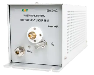
Within approved XGY product content, EM5040E/A/B cover the listed 9 kHz–30 MHz conducted-emissions workflow, 0–264 VAC, 0–375 VDC, 16 A rating, and 50-ohm BNC output. EM5040A includes the listed 10 dB limiter with a 130 dBµV threshold and optional 9 kHz/150 kHz high-pass filtering. EM5040C has a different boundary: 100 kHz–200 MHz, 0–250 VAC, 0–600 VDC, 100 A rated current, listed 500 A short-time current, and 50-ohm N output. These values remain model-specific and must be confirmed against approved data and the DUT method.
The YSA real-time spectrum-analyzer family can support debug and pre-compliance review when its selected configuration, detector/settings, dynamic range, protection, frequency coverage, and export workflow meet the task. A useful analyzer does not remove the need for the correct coupling network, controlled setup, valid limit, correction chain, or formal compliance process.
Common failure modes
- The wrong detector or bandwidth is compared with a valid-looking limit line.
- The receiver is overloaded by the fundamental or transient from the DUT power path.
- A limiter or cable loss is present physically but absent from corrections, or applied twice.
- DUT revision and operating mode are recorded, but support equipment and cable geometry are not.
- An ambient signal is assigned to the DUT without state correlation or baseline evidence.
- Peak pre-scan data is presented as a final quasi-peak/average result.
- A calibrated analyzer is assumed to make an uncontrolled setup compliant.
Source-to-claim map
| Claim area | Primary-source basis | Boundary retained |
|---|---|---|
| Measuring apparatus and spectrum-analyzer characteristics matter | CISPR 16-1-1 | The article does not assert that every analyzer configuration is a compliant EMI receiver |
| LISNs/coupling devices and conducted methods have controlled characteristics | CISPR 16-1-2 and CISPR 16-2-1 | Product-specific setup and full method remain necessary |
| Instrumentation uncertainty affects disturbance-limit decisions | CISPR 16-4-2 | No universal uncertainty or formal verdict is assigned here |
| US line-conducted requirements depend on the FCC rule context | FCC KDB 174176 and Federal Register rulemaking | The article is not US legal advice or equipment-authorisation evidence |
| Laboratory competence is broader than owning calibrated equipment | ISO/IEC 17025 | Pre-compliance work is not described as accredited testing |
Product fit
Where XGY Tek fits
XGY Tek can help scope a repeatable EMC pre-compliance bench around the verified LISN and spectrum-analyzer options below. Final suitability depends on the DUT power path, measurement bandwidth, limits, accessories, setup controls, and acceptance requirements; formal compliance remains within the applicable competent or authorised test process.
RF Accessories
EM5040 Series LISN
XGY EM5040 is a family of V-type line impedance stabilization networks designed for conducted disturbance voltage measurement in EMC testing. The series supports R&D debugging, compliance validation, receiver protection, CM/DM analysis, and high-current EMC workflows.
View product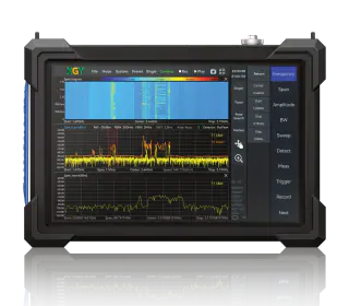
Spectrum Analyzers
YSA-P400 Spectrum Analyzer
XGY YSA-P400 is a handheld portable precision real-time spectrum analyzer for 9 kHz to 40 GHz RF analysis. It delivers -161 dBm/Hz DANL, 100 MHz analysis bandwidth, and a 1.5 kg portable form factor for 5G network maintenance, radar testing, interference hunting, and EMC pre-compliance.
View productFAQ
Frequently asked questions
Can a pre-compliance bench replace a certified EMC lab?
No. A pre-compliance bench is an engineering debug and design-comparison tool, not a substitute for formal compliance testing. Its value is repeatable evidence: which mode produced the emission, which design change reduced it, what margin was observed under the chosen limit line, and what setup produced the trace.
What does the LISN contribute to a conducted-emissions setup?
The LISN provides a defined impedance and measurement point between the DUT power input and the analyzer path. For a useful setup, the buyer still has to define voltage, current, phase, grounding, unused-port termination, RF-output protection, and the physical cable layout around the DUT.
Which analyzer settings must be recorded in the report?
Record start and stop frequency, RBW, VBW, detector mode, sweep time, attenuation, preamp state, trace mode, limit line, antenna or LISN path, cable notes, and any correction factors. A screenshot without these settings is weak evidence because another engineer cannot reproduce the measurement.
When should a pre-compliance setup become automated?
Automation is justified when multiple revisions, operators, operating modes, or product variants must be compared under the same conditions. If the team only needs occasional debug scans, a manual setup with a disciplined checklist may be sufficient; if the data supports release gates, automated settings recall and report generation are usually worth scoping.
Keep exploring
Related technical resources
Related articles
Technical Article
Handheld Spectrum Analyzer Checklist for Field RF Troubleshooting
A practical checklist for choosing a handheld spectrum analyzer for interference hunting, 5G checks, EMC pre-compliance, and field RF troubleshooting.
Read article
Technical Article
Automated Test Rack Acceptance Plan for Australian-Made Systems
How to define acceptance criteria for Australian-made automated test racks, including measurements, safety, reports, FAT/SAT evidence, and export review.
Read article
Procurement Checklist
RF Test Equipment RFQ Checklist for Global Buyers
A practical RFQ checklist for RF test equipment buyers covering frequency range, bandwidth, power, calibration, fixtures, acceptance evidence, and export screening.
Read article