
In brief
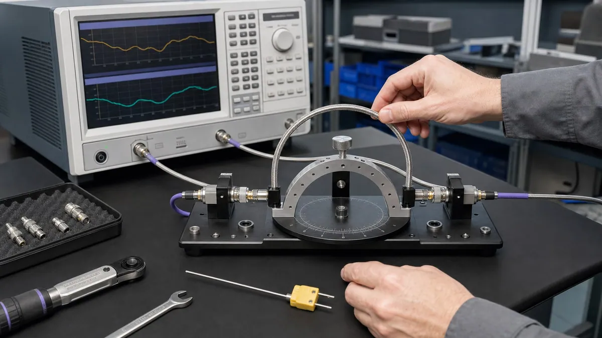
Select a phase-stable RF test cable for its actual measurement role and movement profile, not frequency rating alone. Frequency and connector fit, insertion and return loss, stability under flex, bend radius, shielding, strain relief, calibration plane, and maintenance all need to be accepted under the way the cable will really be handled.
Key takeaways
- Define whether the cable is fixed, occasionally moved, or flexed every test cycle, and record bend, routing, connector, length, and calibration-plane requirements.
- Compare electrical performance and mechanical behaviour together because a high-frequency cable can still be unsuitable for a moving fixture or precision VNA path.
- Acceptance should pair an electrical baseline with representative flex or load-and-unload checks, connector controls, path-health verification, and a spare strategy.
An RF test cable is not a transparent accessory: it is a two-port network inside the measurement. The correct buying question is therefore not “which cable has the highest frequency?” but “how much phase and magnitude change may this complete assembly introduce, under a defined movement and environment, without changing the DUT decision?” That question leads to a testable requirement and prevents nominal bandwidth from being mistaken for stability.
Define phase stability before comparing numbers
Electrical phase is related to electrical length. For a uniform line, a small physical or effective-length change produces approximately
Delta phi = 360 f Delta l / v_p,
where Delta phi is in degrees, f is frequency, Delta l is the change in effective length, and v_p is propagation velocity. Rearranging gives Delta l = v_p Delta phi / (360 f). This is a sensitivity relation, not a cable specification: bending can also change impedance, dielectric state, connector geometry, and loss.
An absolute phase value at one routing position is different from phase stability. A purchasing specification should say whether it means:
- change after one controlled bend and return;
- maximum excursion while a cable moves through a fixture cycle;
- change over a temperature range after thermal soak;
- drift over elapsed time at a fixed route;
- phase tracking between two or more assemblies; or
- repeatability after disconnecting and reconnecting the interface.
These measurands are not interchangeable. IEC 61196-1-111:2024 identifies test-method categories for phase change with temperature, bending, twisting, and consistency among multiple cables. The useful lesson for an RFQ is methodological: name the stimulus, reference state, frequency points, sample count, conditioning, and calculation. A statement such as “phase stable to 3 degrees” is incomplete without those conditions.
Group delay is another related but distinct quantity. It is defined as tau_g = -d phi / d omega. A cable may show a small phase change at a single frequency yet alter phase slope across a band. If the DUT decision depends on delay, modulation, time-domain gating, or a wideband transfer function, include group-delay or bandwise phase criteria rather than relying on one spot frequency.
Convert the station workflow into a movement profile
Classify each assembly by what actually happens after calibration. A static metrology lead may be dressed once and mechanically restrained. A probe-station lead moves when the probe arm lands. A production cable may bend every load cycle. A field lead is coiled, transported, and reconnected. Each role has a different dominant risk.
Document cable length, supported and moving segments, connector exit direction, minimum bend radius, bend mandrel or fixture geometry, bend angle, number and rate of cycles, torsion, crush points, and strain-relief locations. Photographs or a routing drawing are better than the word “flexible.” Also state whether the cable returns to the same route before the reading or is measured while moving. A return-to-position test can hide transient excursion that matters in an antenna scanner or moving test head.
Temperature belongs in the movement profile even in an ordinary laboratory. Define the cable temperature, gradient, air flow, warm-up time, and whether operators touch or move it. For a chamber feedthrough, separate the section exposed to temperature from the room-temperature section. Do not apply a supplier’s bend result to temperature stability, or a room-temperature result to a chamber path, unless the test conditions support that inference.
Treat the connector and calibration plane as part of the assembly
Connector family sets an interface and frequency boundary, but condition and mating practice set repeatability. Specify family, sex, pin depth or interface requirements where relevant, mating torque, allowed adapters, expected mating cycles, inspection criteria, and who owns replaceable adapters. IEEE 287.1 and 287.3 provide the standards context for precision coaxial interfaces and recommended practice. They do not make a damaged connector repeatable.
Place the calibration plane explicitly on a drawing. If calibration ends at the instrument port and the cable remains in the measured path, the cable response is part of the result. If calibration ends at the cable tip, residual errors still include calibration-standard models, connection repeatability, drift, noise, and post-calibration movement. If the cable is disconnected after calibration, the reconnection is a new uncertainty contribution. De-embedding a stored cable S-parameter file can remove a nominal response but cannot correct an unpredictable state change.
Electrical comparison should include insertion loss and its ripple, return loss or VSWR, phase or group delay, power level, shielding/isolation requirement, and mode-free operating band. Quote the full connectorised assembly, not bulk cable alone. At high frequency an adapter, launch, or worn interface can dominate a premium cable.
Build an uncertainty and decision budget
Define the DUT measurand first, then allocate a permissible station contribution. A practical phase-repeatability study may include VNA trace noise, calibration residuals, reference-standard uncertainty, connector remating, cable movement, temperature, fixture repositioning, and analysis repeatability. Under the JCGM framework, independent standard-uncertainty components are often combined by root-sum-square; correlated terms and non-statistical limits require an appropriate model. A worst-case arithmetic sum is conservative but should not be presented as a statistical uncertainty.
Do not set the cable acceptance limit equal to the entire guard band between pass and fail. Leave capacity for all other path terms and for long-term drift. For example, if a product limit is 20 degrees and conforming units are expected to approach 18 degrees, a cable permitted to move 3 degrees can reverse the decision even before fixture and calibration effects are counted.
| Use case | Dominant cable question | Minimum evidence before selection |
|---|---|---|
| Fixed VNA bench | Does the routed path stay unchanged after calibration? | Connector inspection, baseline S-parameters, route restraint, verification standard result |
| Repeated fixture loading | What phase and magnitude excursion occurs through the real load/unload motion? | Defined motion fixture, before/after and cycle data, bend geometry, cable ID and temperature |
| Multi-channel or differential path | Do assemblies track one another as they move and age? | Pair/group tracking data, matched route, connector/remating controls |
| Chamber or outdoor path | How do temperature and gradients change electrical length and loss? | Temperature profile, soak, measurement method, recovery and hysteresis data |
| Field kit | Does transport, coiling, and reconnection preserve a verified state? | Storage radius, inspection method, remating study, portable verification artefact |
Use a reproducible incoming and periodic acceptance method
Record cable serial or asset ID, model, length, connector interfaces, calibration kit and coefficients, VNA identity, calibration date, power, IF bandwidth, averaging, frequency grid, ambient conditions, route fixture, and operator. Inspect and clean interfaces using the approved procedure before the baseline. Calibrate at the declared plane, then measure a suitable verification device that was not merely one of the standards used to solve the calibration.
Capture the cable baseline without smoothing away ripple. Apply the defined bend, twist, load/unload, or temperature stimulus and repeat enough times to estimate repeatability. Calculate signed change and maximum absolute change at every required point; an average can conceal a narrow-band failure. If phase is unwrapped, preserve the raw complex data and document the unwrap algorithm. Record magnitude change alongside phase because a damaged line can show both.
Set stop rules for damaged plating, loose coupling nuts, abnormal mating feel, failed verification, or an exceeded phase/magnitude limit. Recalibration should not automatically erase a cable failure: first determine whether the path changed, the calibration failed, or the verification artefact moved. Periodic checks should be triggered by elapsed time, use, connector events, an abnormal golden-device trend, or mechanical incident—not by calendar alone.
Common failure modes
- A supplier number is copied without its bend diameter, frequency, length, temperature, or test sequence.
- The cable is accepted straight on a bench but bent differently in the fixture.
- Phase is measured after returning the cable to rest, while the station measures during motion.
- Reconnection variation is attributed to cable flex, or flex variation is hidden by recalibration.
- An adapter is added after acceptance and its repeatability is not included.
- A single sweep is called stability even though no controlled stimulus or repetition occurred.
- Operators over-torque, side-load, or rotate the cable body while mating the connector.
- A de-embedding file is treated as compensation for damage or state-dependent change.
Illustrative worked example: translating degrees into sensitivity
This numerical example is illustrative engineering arithmetic, not an XGY cable measurement or customer result. Assume a propagation velocity of 0.70c, frequency of 10 GHz, and an allowed cable phase change of 1 degree. The equivalent effective-length change is
Delta l = (0.70 x 299,792,458 x 1) / (360 x 10^10) = 0.0000583 m,
or about 0.058 mm. At 20 GHz the same 1-degree limit corresponds to about 0.029 mm for the same assumed velocity. The calculation explains why routing, connector support, and temperature can matter even when no visible damage exists. It does not predict a particular cable’s bend stability; that requires measured evidence under the specified stimulus.
An acceptance plan might reserve 1.0 degree for cable movement, 0.6 degree for remating, 0.5 degree for calibration and verification repeatability, and 0.4 degree for fixture repositioning. If these were justified as independent standard uncertainties, the root-sum-square would be about 1.33 degrees; if they are only maximum limits, that calculation is not valid and a 2.5-degree worst-case sum may be the safer planning value. The distinction must be stated.
Source-to-claim map
| Engineering statement in this article | Primary or official basis |
|---|---|
| Phase-stability methods must distinguish temperature, bending, twisting, and multi-cable consistency | IEC 61196-1-111:2024 |
| Precision connector interface and handling practices affect measurement repeatability | IEEE 287.1-2021 and IEEE 287.3-2021 |
| Reference-plane calibration requires defined standards and residual-error control | NIST multireflect-thru calibration research |
| Precision coaxial standards have dimensional and model uncertainty | NIST 2.4 mm airline traceability research |
| The measurand and uncertainty contributions should be explicitly defined | JCGM GUM and VIM |
| Competent calibration operation involves method and quality controls, not equipment ownership alone | ISO/IEC 17025:2017 |
XGY product-data boundary
XGY product pages separate three families rather than asserting one universal cable. The VT Series is listed from DC to 67 GHz; its published table gives connector- and model-dependent VSWR and phase-stability values, including values evaluated with a stated 10 cm mandrel condition. The PT Series is listed through 110 GHz; published phase-stability values are model dependent for PT40, PT50, and PT67, while PT110 requires confirmation rather than extrapolation. The GL Series is listed through 26.5 GHz and publishes band-dependent phase and amplitude-stability information plus a 20 mm bend condition.
Those are product-data boundaries, not proof of performance in the reader’s fixture. Frequency, assembly length, connector pair, bend method, temperature, cycles, calibration, and acceptance limit must match the quoted configuration. No family-wide flex life, universal phase value, or system-level measurement uncertainty is claimed here.
Product fit
Where XGY Tek fits
The listed VT, PT, and GL cable families can be reviewed against the frequency, connector, length, movement, bend, phase-stability, insertion-loss, shielding, and calibration requirements of the actual test path. The highest frequency rating alone does not establish phase stability, flex life, or measurement suitability.
RF Accessories
VT Series Precision VNA Test Cable
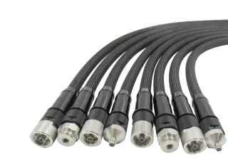
XGY VT Series is a vector network analyzer test cable family covering DC to 67 GHz by configuration, for precision VNA applications. Ruggedized stainless-steel armor, triple shielding, and stable phase and loss performance support repeatable measurement under dynamic flexure.
View product
RF Accessories
PT Series Precision Test Cable
XGY PT Series is a precision RF and mmWave test cable family for measurement interconnects covering DC to 110 GHz by configuration. The series uses a ruggedized 10-layer armored construction for electrical repeatability, phase stability, low insertion loss, and durable R&D, calibration, and field use.
View product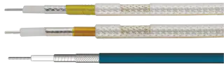
RF Accessories
GL Series Phase-Stable Test Cable
XGY GL is a phase-stable RF test cable series for interconnects covering DC to 26.5 GHz by configuration, using proprietary flat silver-plated tape shielding for strong phase and amplitude stability in outdoor base-station and harsh-environment setups.
View productFAQ
Frequently asked questions
When is a phase-stable cable worth specifying?
A phase-stable cable is worth specifying when the cable moves after calibration or when small phase and amplitude changes affect the measurement decision. Common cases include VNA fixtures, antenna measurement, semiconductor probing, moving test heads, and production stations where cable flex happens during every load cycle.
How should bend radius be handled in the quote?
State the expected routing, minimum bend radius, cable length, connector exit direction, moving sections, and strain-relief points. Bend radius is not just a mechanical comfort issue; over-bending can change RF performance, shorten cable life, and make calibration drift look like DUT variation.
What is a practical incoming inspection for RF test cables?
Incoming inspection should check connector condition, labeling, length, insertion loss, return loss, and compatibility with the calibration method. For a moving fixture cable, add a repeatability check after controlled flexing or fixture load/unload cycles so the handling condition matches the real station.
How should production teams protect VNA ports?
Use defined torque practice, sacrificial adapters, protective caps, strain relief, spare assemblies, and a path-health check with a known standard or golden device. These controls reduce downtime and prevent connector wear from being mistaken for product drift.
Keep exploring
Related technical resources
Related articles
Technical Article
Choosing a PXIe VNA for Production RF Test
A buyer-focused guide to choosing PXIe vector network analyzers by frequency range, port count, dynamic range, slot width, and automation workflow.
Read article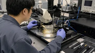
Technical Article
Manual Probe Station Checklist for Wafer-Level Test
What to check before buying a manual probe station for semiconductor wafer, RF probe, and device characterization workflows.
Read article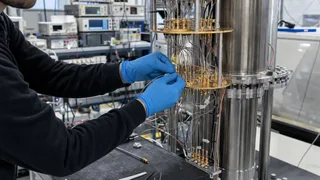
Technical Article
Cryogenic Quantum Interconnect Selection Questions
Key questions for selecting cryogenic RF interconnects for dilution refrigerators, quantum control lines, and low-temperature measurement systems.
Read article