
In brief
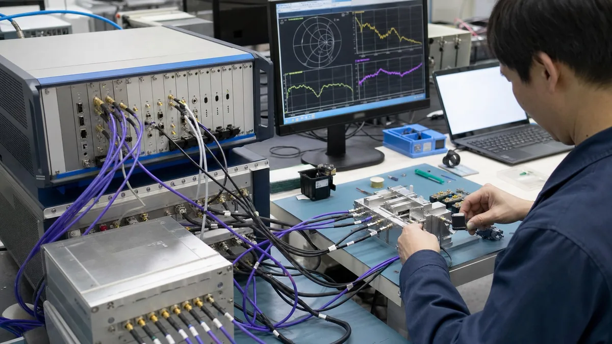
Choose a PXIe VNA for production from the DUT path map and station workflow, not the highest frequency specification. Required S-parameters, port and switch topology, calibration plane, slot budget, fixture movement, cycle time, software control, and traceable data output determine whether the full rack is production-ready.
Key takeaways
- Map required DUT paths and S-parameters before choosing port count, switching, frequency coverage, dynamic range, and PXIe slot allocation.
- Define calibration, fixture compensation, cable movement, connector protection, and path-health checks as part of the production station.
- Accept the rack with known-good and known-fail samples, repeatability and full-cycle timing, failed-calibration handling, and auditable result records.
A PXIe VNA becomes production equipment only when its RF topology, reference plane, automation, timing, uncertainty, and failure handling are defined as one station. Upper frequency is a necessary boundary, not a production-readiness score. Start with the DUT path map and the decision the measurement must support, then select ports, switching, module bandwidth, fixture treatment, and software.
Define the measurand and path map first
List every physical DUT port and every required complex S-parameter. Separate reflection, forward and reverse transmission, isolation, group delay, gain/flatness, balance, and mixed-mode results. State frequency grid, source power at the DUT plane, IF bandwidth, averaging, receiver range, and whether limits apply to every point, a band statistic, or a derived marker. “Measure insertion loss” is not complete enough to reproduce a test.
Draw the signal path for every state: VNA port, protection adapter, cable, relay or switch, fixture launch, trace, connector, and DUT. Mark which elements move or reconnect. A two-port module can measure many ports sequentially through a matrix, but each relay path adds loss, mismatch, repeatability, settling, and calibration work. Direct multi-port measurement can reduce switching and reconnection, but uses more chassis capacity and may still need routing for DUT count or protection.
Port count should therefore be chosen from states and simultaneous relationships, not connector count alone. Differential or multi-port devices may require mixed-mode transformation; that transformation is only meaningful if all contributing single-ended paths share a valid calibration and consistent phase reference. If the product decision depends on time alignment or a changing state, define whether measurements must be coherent or merely sequential.
Interpret analyzer specifications in their stated conditions
Frequency coverage must include the measurement band, fixture or calibration guard band, and any harmonics or out-of-band checks actually required. Do not buy unused bandwidth at the expense of port topology or workflow, but do not place a production limit at an undocumented edge of the configured system.
Dynamic range is not a single universal DUT capability. Published values may depend on frequency, IF bandwidth, averaging, source level, receiver path, and definition. The usable station floor also includes switch isolation, fixture leakage, crosstalk, source harmonics, environmental coupling, and drift. Likewise, trace noise, measurement speed, power accuracy, and receiver compression must be compared under conditions resembling the production recipe.
Resolution is not accuracy. A narrow display increment or dense frequency grid cannot correct calibration residuals, connector repeatability, fixture errors, or DUT loading. Ask for the specification conditions and translate them into an uncertainty or capability study for the actual measurand.
Put calibration and de-embedding on the path drawing
The calibration plane is where systematic VNA errors are corrected by the chosen method; the DUT reference plane is where the result is intended to apply. They may coincide at coaxial connectors, but a fixture or probe often separates them. State the calibration method, standards and definitions, kit coefficients, port assignment, power, frequency grid, and environmental conditions. Save enough metadata to reconstruct the calibration state.
SOLT, TRL-family, and multi-reflect approaches solve different physical constraints. The right method depends on accessible standards and the transmission medium; the method name alone does not establish uncertainty. NIST’s multireflect-thru work illustrates that calibration depends on standards and error modelling, while IEEE 370 addresses characterization and de-embedding of interconnect structures. A de-embedded fixture model must have a defined topology, reference impedance, frequency validity, orientation, version, and validation artefact.
Verification is independent of calibration. Measure a check standard or verification device that can reveal a bad connection, wrong kit definition, damaged path, or drift. A golden DUT can monitor the station, but if its value is assigned only by the same station it cannot by itself provide independent traceability. Define warning and stop limits and block production after a failed verification until the cause is resolved.
Connector handling is part of calibration control. Record inspection, cleaning, gauge or dimensional checks where appropriate, torque practice, adapter ownership, and mating history. IEEE 287.3 provides recommended-practice context for precision coaxial connectors. Recalibrating after a damaged or contaminated interface is not a repair.
Budget uncertainty and guard the decision
Build the model around the reported quantity. For a transmission-magnitude result, relevant terms may include calibration residuals, trace noise, source-power dependence, drift, connector remating, switch repeatability, cable movement, fixture de-embedding, temperature, and sample positioning. Phase and group-delay results may have different dominant terms. Correlation across frequency and paths matters; point-by-point repeatability is not automatically uncertainty of a band-derived result.
The JCGM GUM framework supports combining evaluated standard-uncertainty components with an explicit measurement model. Production teams may also use measurement-system analysis or empirical station correlation, but should not label a simple range or worst-case sum as a statistically expanded uncertainty. Define the coverage or decision rule used.
Guard bands should protect against false acceptance at the product limit. If the allowed DUT limit is L and the validated decision allowance is g, a simple upper acceptance limit might be L - g; the value of g must come from the risk policy and measurement evidence, not a universal formula. Keep engineering characterization limits, production-screen limits, and station-health limits separate.
Calculate full station cycle time
Analyzer sweep time is only one term. A useful model is
T_cycle = T_load + T_identify + T_route + T_settle + T_sweep + T_compute + T_verify + T_store + T_unload + T_recovery.
Multiply state-dependent terms by the number of paths and recipes. Include switch settling, power-level changes, source dwell, fixture actuation, barcode retries, report generation, error queries, and database latency. Report median and upper-percentile cycle time during a sustained run; a single best case does not size production capacity.
PXI provides a modular platform and shared timing/trigger resources, but the system design must allocate controller bandwidth, chassis slots, cooling, power, trigger lines, switch modules, and spares. Check that the intended trigger route and module combination are supported in the selected chassis. PXI membership or compatibility branding does not prove timing performance of a specific assembled rack.
Design automation for controlled failure
Specify the control layer—SCPI, IVI driver, vendor API, or another supported interface—and pin versions. SCPI standardizes command structure, not identical command coverage. IVI architecture can isolate application logic from instrument I/O, but interchangeability still requires testing of attributes, error behaviour, triggering, calibration access, and binary data formats.
The sequence should check status and error queues, enforce timeouts, identify modules, validate recipe/module compatibility, verify calibration age and health, and move hardware to a safe state after abort. Store DUT ID, path, raw complex trace or justified derived data, limits, decision, calibration ID, de-embedding version, module serials, fixture ID, software/recipe version, timestamps, and retest lineage. Never overwrite an initial fail with a passing retest without retaining both records and the authorised retest reason.
| Design choice | Prefer it when | Evidence required |
|---|---|---|
| Direct two-port | One RF path is measured and remating is controlled | Path map, frequency/power coverage, cycle-time and repeatability study |
| Two-port plus switch | Many sequential paths tolerate switch loss and settling | Path-by-path calibration/verification, isolation and repeatability, switch-life plan |
| Four- or six-port | Multiple relationships, reduced remating, or phase consistency justify direct ports | Full multi-port calibration, crosstalk study, slot/thermal budget |
| Fixture de-embedding | DUT planes are inaccessible and fixture structures can be characterized | Validated fixture model, reference-plane definition, version and verification artefact |
| Marker-only storage | Derived values are demonstrably sufficient for investigation and quality records | Retention rationale plus sampled/full-trace escalation rule |
Failure modes that should block release
- A module is chosen by maximum GHz while the DUT requires more direct ports or less switching.
- Dynamic range is copied without the bandwidth, frequency, power, or receiver conditions.
- The reference plane is described verbally but not shown through cables, switches, and fixture.
- Calibration passes, but no independent verification or stop rule exists.
- A stored fixture file is applied with the wrong port order, orientation, revision, or frequency range.
- Total takt time omits load, route, settle, storage, and retry behaviour.
- Operators can change power, bandwidth, limits, or calibration files outside recipe control.
- A failed unit is retested until it passes and the earlier result disappears.
Illustrative worked example: topology versus cycle time
This example is hypothetical engineering arithmetic, not measured YNA performance or a customer result. Consider a six-port DUT requiring twelve directed transmission paths plus six reflections from 100 MHz to 8 GHz. Architecture A uses a two-port VNA and a switch matrix; assume 40 ms switching/settling and 85 ms sweep/processing per state, 18 states, plus 2.2 s common load, identification, storage, and unload time. Its estimated cycle is 18 x (0.040 + 0.085) + 2.2 = 4.45 s before retries.
Architecture B uses six direct ports; assume three coherent measurement groups at 145 ms each plus the same 2.2 s common work. Its illustrative estimate is 3 x 0.145 + 2.2 = 2.635 s. That 1.815 s difference may justify direct ports, but only if calibration duration, chassis slots, module cost, port isolation, trace noise, and maintenance evidence also satisfy the requirement. Substitute measured timing distributions from the candidate rack; these assumed values must not appear in a purchase specification as product data.
Source-to-claim map
| Engineering statement in this article | Primary or official basis |
|---|---|
| PXI is a modular instrumentation platform with ecosystem specifications | PXI Systems Alliance |
| Driver and application layers can be separated, subject to validated behaviour | IVI specifications and driver architecture |
| SCPI standardizes programmable-instrument command structure but not identical coverage | IVI Foundation SCPI overview |
| Fixture/interconnect characterization and de-embedding require defined reference planes | IEEE 370-2020 |
| VNA calibration requires explicit standards and error modelling | NIST multireflect-thru research |
| Precision connector handling affects repeatable coaxial measurement | IEEE 287.3-2021 |
| Measurement uncertainty requires a defined measurand and contribution model | JCGM GUM and VIM |
| Competent laboratory operation includes method and quality controls | ISO/IEC 17025:2017 |
XGY product-data boundary
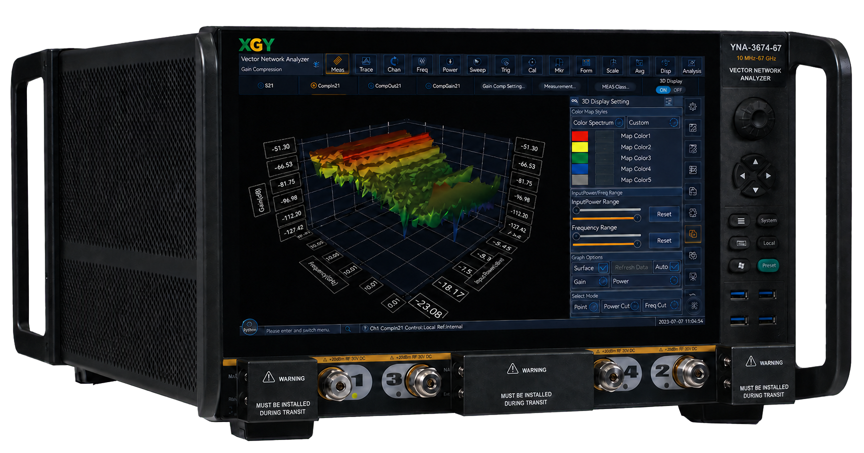
The currently published XGY vector network analyzer is the YNA-3674 series, a benchtop instrument whose frequency ceiling is fixed by the configured model across 10 MHz to 120 GHz, with two ports standard and a four-port measurement configuration available. PXIe VNA modules are supplied to order rather than listed. These facts support topology shortlisting only.
They do not prove rack-level dynamic range, uncertainty, mixed-module compatibility, sweep time, takt time, cooling adequacy, software interoperability, calibration validity, or production yield. Those outcomes depend on the exact configuration and acceptance evidence. Any additional model specification used in a quote should be tied to the applicable product revision and its stated test conditions.
Product fit
Where XGY Tek fits
The published YNA-3674 series can be reviewed against the required frequency range, DUT path map, port topology, dynamic range, slot budget, calibration plane, fixture, cycle time, and software workflow. Instrument specifications alone do not establish rack throughput, repeatability, or production readiness; those outcomes require system-level acceptance evidence.
FAQ
Frequently asked questions
How should port count be chosen for a production VNA station?
Choose port count from the DUT RF path map and the fixture workflow. A two-port VNA can work when switching or sequential measurement is acceptable. A multi-port VNA is usually justified when connector changes, switch settling, MIMO paths, differential structures, or production cycle time make re-mating or heavy switching risky.
What is the calibration plane in a PXIe VNA rack?
The calibration plane is the point where measurement uncertainty is controlled for the DUT result. In a production rack it may sit at the VNA port, after a cable, after a switch matrix, or at the fixture launch. The quote should state the plane explicitly because cables, relays, adapters, and probes can dominate the final result.
What should a VNA rack acceptance test include?
Acceptance should include known-good and known-fail samples, repeated runs, calibration verification, path-health checks, fixture loading, cycle-time measurement, data export, and report review. A clean trace on one device does not prove the station is ready for production.
When is a higher-frequency VNA not the right answer?
A higher-frequency VNA is not the right answer when the real bottleneck is port count, switching loss, fixture repeatability, calibration time, slot budget, or data handling. Frequency coverage must be mandatory for the DUT, but it should not hide a poor production topology.
Keep exploring
Related technical resources
Related articles
Technical Article
Phase-Stable RF Test Cable Buying Guide
How to evaluate phase-stable RF test cables for VNA measurement, production test, field use, and mmWave benches.
Read article
Technical Article
Custom Test Fixture Scoping Before Quotation
What engineering teams should provide before requesting a custom RF, power, semiconductor, or electronics test fixture quote.
Read article
Technical Article
Automated Test Rack Acceptance Plan for Australian-Made Systems
How to define acceptance criteria for Australian-made automated test racks, including measurements, safety, reports, FAT/SAT evidence, and export review.
Read article