
In brief
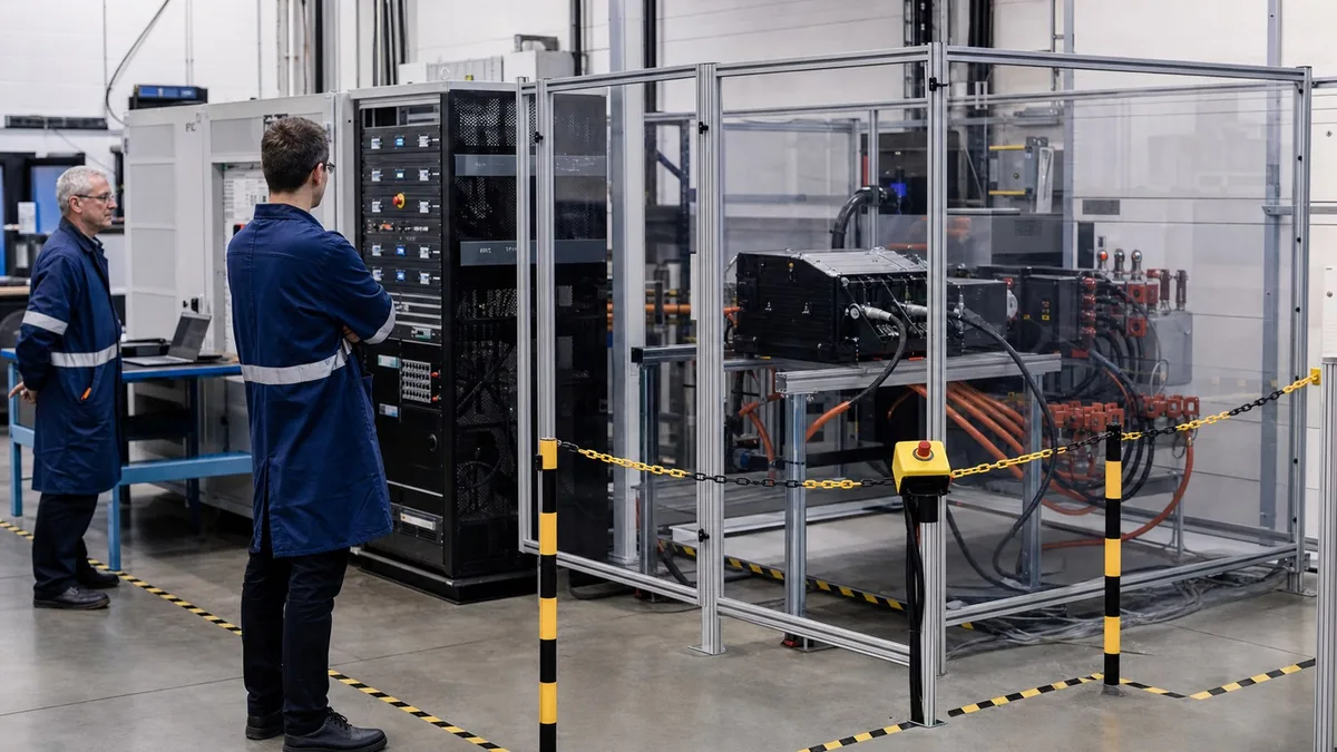
Plan a regenerative AC/DC source as a complete energy-handling bench: define the source and sink envelope, grid waveforms, facility and safety constraints, controls, reporting, and acceptance tests together. A source rating alone does not establish whether the system can handle returned energy or required fault cases.
Key takeaways
- Document voltage, current, power, phase, frequency, waveform, duration, and returned-energy profiles across startup, steady state, transients, faults, and shutdown.
- Review facility power, grounding, protection, emergency stop, cooling, guarding, and regenerative site compatibility before the final configuration is approved.
- Acceptance should separately prove output behavior, regenerative events, waveform sequences, fault handling, data export, and site-specific commissioning requirements.
A regenerative AC/DC source sits between a DUT and a facility, and both interfaces can exchange energy. That makes source selection a system-engineering problem. The DUT may draw power, return power, change power factor, generate harmonics, or disconnect unexpectedly. The facility must supply, accept, or safely reject those conditions while protection and measurement remain valid. A catalogue kVA value cannot describe that interaction.
Start the requirements document with three diagrams: a power single-line, a control/state diagram, and a measurement/data diagram. The single-line shows energy paths, isolation, protection, contactors, grounding, and access points. The state diagram shows normal and abnormal transitions. The data diagram shows where voltage, current, power, waveform, event, and configuration records originate. Together they reveal assumptions that a block labelled “grid simulator” hides.
Calculate the steady-state envelope correctly
For DC, instantaneous power is P_DC = V_DC x I_DC. For a balanced three-phase sinusoidal system, apparent power is S = sqrt(3) x V_LL x I_L, where V_LL is line-to-line RMS voltage and I_L is line RMS current. Active power is P = S x PF, where PF is true power factor. The familiar formula is not sufficient for deliberately distorted or unbalanced waveforms; use per-phase, time-domain measurements and the project’s defined method.
The source worksheet should contain source and sink limits for:
- AC and DC voltage, including range changes, phase-to-neutral and line-to-line definitions;
- per-phase current, neutral current where applicable, continuous and time-qualified overload;
- active power, reactive power, apparent power, and power-factor range;
- single-, split-, or three-phase topology, phase sequence, phase angle, and unbalance;
- fundamental frequency, slew, phase jump, and recovery trajectory;
- harmonic/interharmonic content, crest factor, DC offset, and waveform bandwidth;
- regenerative power, returned energy, duration, transition through zero power, and facility response;
- DUT inrush, pre-charge, anti-islanding or disconnect behaviour, and residual stored energy.
Do not infer current from kVA without the selected voltage and phase configuration. Do not infer active power from kVA without power factor. Do not infer regenerative capacity from source capacity unless the product data states both directions under the relevant conditions.
Turn “grid simulation” into a waveform table
A reproducible waveform request names the initial condition, event, duration, phase relationship, recovery, repetition, DUT operating mode, and pass criterion. At minimum, distinguish steady variation, ramp, step, dip, interruption, phase jump, frequency variation, harmonic/interharmonic content, unbalance, and return-to-normal behaviour.
IEC 61000-4-11 and IEC 61000-4-34 illustrate why current scope matters: the former addresses equipment up to 16 A per phase, while the latter addresses equipment above 16 A per phase, within their stated network conditions. IEC 61000-4-13 addresses harmonics and interharmonics immunity within its scope. These are basic test methods, not universal product limits. The relevant product standard or customer method determines which tests, levels, durations, phase selections, and performance criteria apply.
| Waveform field | Requirement example format | Why it matters |
|---|---|---|
| Initial condition | Voltage, frequency, phase, load, DUT mode, and stabilisation time | The same event can produce a different DUT response from a different operating state |
| Event definition | Residual voltage or target waveform, affected phase(s), transition, and duration | “Dip test” alone cannot be programmed or reviewed |
| Recovery | Step/ramp shape, phase continuity, overshoot allowance, and observation window | Recovery may be more stressful than the event itself |
| Repetition | Count, interval, phase angle, and random/fixed timing | Defines thermal accumulation and statistical coverage |
| Verdict | Measured function, allowed degradation, recovery time, and data window | Prevents a subjective “looked stable” conclusion |
Engineer the returned-energy path
Choose a sign convention and retain directional energy separately. If positive power means facility-to-DUT, returned energy over a sink interval is E_return = integral(-P(t) dt) while P(t) < 0. A sampled implementation can use sum(-P_k x delta_t_k) over negative-power samples. This is energy at the defined measurement plane, not necessarily the energy credited by a utility meter.
Ask what happens when the facility cannot accept returned energy, when a breaker opens, when phase is lost, when voltage leaves the regenerative operating window, or when the source reports a grid-side fault. The DUT may still contain DC-link, magnetic, rotating, or battery energy. The safe design may need coordinated current reduction, contactors, a discharge path, a braking element, or another containment method selected by risk assessment.
Regeneration also changes facility review. Confirm incoming supply topology, protective earth, available fault current, protective-device coordination, leakage/residual-current considerations, permitted reverse flow, transformer or generator constraints, power-quality rules, cooling, acoustic limits, and emergency isolation. A source that operates correctly at factory acceptance can still be unsuitable at the installation if these conditions differ.
Pre-quote bench scope matrix
The quotation package should close the main energy-path and workflow questions before it assigns product models. This is a scope-readiness check, not a substitute for the later acceptance matrix.
| Scope area | Evidence to provide | Rework trigger |
|---|---|---|
| Operating envelope | AC/DC voltage, current, continuous and peak power, phase, frequency, profile duration, transient requirements, and thermal state | The request confirms only headline power and omits source, sink, transient, or duration limits |
| Regenerative behaviour | Returned-power and energy profile, sink current, sink power, facility-side state, abnormal-operation response, and site approval boundary | The DUT can return energy but the facility path or trip behaviour is undefined |
| Fault response | Applicable over-limit, temperature, contactor, communications-loss, emergency-stop, profile-abort, and safe-discharge cases with expected end states | Protection relies on software alone or leaves stored energy without a documented verified-safe state |
| Data and reporting | DUT ID, profile, source settings, measured voltage/current/power, fault state, operator, timestamps, software version, and instrument identities | The report proves a verdict but cannot reconstruct how the result was produced |
| Commissioning inputs | Local power, grounding, cooling, cable routing, warning indicators, user roles, and representative DUT workflow | Factory acceptance is expected to close dependencies that exist only at the buyer’s site |
Keep communication conformance separate from power performance
ISO 15118-20 defines network and application-layer communication for EV and EVSE, including message sequences that support bidirectional power transfer. ISO 15118-21 provides common conformance tests for specified communication requirements. Its official scope also makes an important boundary explicit: the conformance plan does not establish power-flow performance, robustness, reliability, or physical implementation quality.
Therefore, a V2G bench may need at least three evidence sets: protocol conformance where applicable, electrical power-transfer behaviour, and system safety/fault behaviour. Passing one does not imply passing the others. The RFQ should state the EVCC/SECC role, supported communication generation, security/material provisioning boundary, message logging, time synchronisation, fault injection, and linkage between protocol events and measured power.
IEC 61851-23 addresses DC EV supply equipment. Its 2023 edition specifies bidirectional-power-transfer requirements for system A; reverse and bidirectional power transfer for systems B and C are not specified in that edition. It should be applied by competent engineers with the relevant edition and full text. It is not authority for describing any generic regenerative source as an IEC 61851-compliant charger.
Safety architecture and commissioning boundary
Define de-energised, ready, energised-idle, sourcing, sinking, controlled-stop, fault-stop, emergency-stop, discharge, and verified-safe states. For each state, list commanded converter mode, contactor positions, protective inputs, access permissions, warning indicators, and reset authority. Include faults in the measurement path itself; an invalid voltage-verification channel must not be treated as proof of zero voltage.
Factory acceptance and site acceptance answer different questions. Factory acceptance can prove the supplier-controlled hardware, software, reports, and simulated interfaces. Site acceptance proves incoming power, grounding, protection, cooling, ventilation, communications, emergency circuits, facility regeneration, and installed cabling. Keep open site dependencies visible rather than marking them “passed” at the factory.
IEC 62477-1 supplies useful power-converter safety context, but the integrated system may also fall under other equipment, installation, vehicle, machinery, EMC, and workplace requirements. Applicable standards must be determined for the actual architecture and jurisdiction. No standard reference in this article is a certification claim.
Measurement uncertainty and data integrity
For sinusoidal steady state, uncertainty contributors can include voltage, current, phase, frequency, range, transducer ratio, channel timing, waveform distortion, and numerical computation. For events, add trigger alignment, sample rate, bandwidth, filter delay, event-duration measurement, and source transient repeatability. For energy, add integration interval and missing-sample handling.
NIST Technical Note 1297 supports listing and combining the components that influence the defined measurand. The report should state the measurement plane and avoid reporting more significant digits than the uncertainty supports. If a pass/fail boundary is close, apply the project’s documented decision rule rather than relying on display resolution.
Retain raw waveform or time-series data, the programmed sequence, source configuration, DUT state, software version, instrument identifiers, calibration status, corrections, uncertainty record, operator, and timestamps. A screenshot alone cannot prove that the programmed and delivered waveforms were equivalent.
Acceptance matrix
| Acceptance area | Evidence required | Hold or reject when |
|---|---|---|
| AC/DC operating envelope | Measured voltage, current, active/reactive/apparent power, phase, frequency, and thermal state at boundary points | Only nominal kVA is demonstrated or one required topology is assumed |
| Waveform events | Programme file plus measured event depth, duration, phase selection, transition, and recovery | Event labels exist but delivered waveform and DUT state are not retained |
| Regenerative event | DUT-side returned power/energy, facility-side state, transition, and grid-fault response | Returned energy has no documented path during facility abnormality |
| Protocol behaviour | Message log, implementation declaration, test case/version, and power-event correlation | Protocol conformance is presented as proof of electrical or safety performance |
| Protection | Forced over-limit, communications loss, contactor mismatch, interlock, emergency stop, and verified-safe state | Reset is automatic or accessible before hazardous energy is verified removed |
| Site commissioning | Incoming power, grounding, protection, cooling, emergency circuit, cabling, and facility return record | Factory evidence is used to close untested installation dependencies |
Illustrative worked example — not a customer case
Assume a fictional balanced 400 V line-to-line, three-phase DUT with a 25 A RMS current requirement. Its apparent-power point is about 17.3 kVA (sqrt(3) x 400 x 25). At a true power factor of 0.95, active power would be about 16.5 kW under the sinusoidal balanced assumption. This shows why a request for “17 kW” is incomplete: the source still needs the required kVA, current, reactive capability, waveform, and unbalance definition.
Now assume the same fictional DUT returns 12 kW for ten minutes. Energy reaching the defined AC/DC source measurement plane is nominally 2 kWh (12 x 10/60) if power is constant. That is not a site-energy saving or grid-export claim. Conversion losses, auxiliaries, cooling, waveform quality, transitions, and facility metering remain outside that simple calculation.
For a 30% residual-voltage event, current demand may change according to DUT control and source limits; it is unsafe to infer current from pre-event power alone. The RFQ would specify event phases, transition, duration, recovery, DUT mode, current limit, and acceptable functional response. Acceptance would compare the programmed event with measured waveform data and record whether the DUT sourced, sank, limited, disconnected, or faulted. All values here are illustrative and are not XGY ratings or customer results.
Product-platform boundary
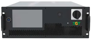
Within approved XGY product content, GXC804B-5K is the compact regenerative AC/DC starting point, with listed configurations from 5 kW to 22.5 kW. The published AC envelope is 0–450 V line-to-neutral from 0.01 Hz to 70 Hz and 0–300 V line-to-neutral above 70 Hz to 1 kHz; the DC range is 0–636 V. Listed AC current is model-dependent: up to 30 A for the 5K single-phase and 15K three-phase configurations, and up to 35 A per phase for the 20K and 22.5K three-phase configurations. The approved content also states THD below 0.5% under its published DC–400 Hz condition and a 4U form factor. Every value remains model- and condition-specific; none proves compatibility with an unstated waveform, DUT, or site.
AC301SHP/AC303SHP is the grid-simulation starting point, with approved content listing 40–250 Hz operation and 0–150 V / 0–300 V phase-voltage ranges. Those ranges do not by themselves establish dip depth, transition, unbalance, harmonic, regenerative, or facility capability. The exact configuration must be checked against the waveform table, phase/current requirement, protective architecture, and commissioning plan.
Source-to-claim map
| Claim area | Primary-source basis | Boundary retained |
|---|---|---|
| Dip/interruption methods depend on per-phase input current scope | IEC 61000-4-11 and IEC 61000-4-34 | Product standard, levels, duration, and performance criteria are not inferred |
| Harmonic/interharmonic immunity needs a defined method | IEC 61000-4-13 | The article does not claim universal waveform coverage |
| EV bidirectional communication and its conformance tests are distinct from power performance | ISO 15118-20 and ISO 15118-21 | Protocol evidence is not represented as electrical, safety, or reliability evidence |
| DC EVSE and converter safety have defined scopes | IEC 61851-23 and IEC 62477-1 | No XGY product certification is claimed |
| Numerical results need uncertainty and full reporting | NIST TN 1297 | The article provides no project-specific uncertainty figure |
Product fit
XGY Tek options for regenerative source and grid-simulation benches
The related GXC804B-5K and AC301SHP/AC303SHP platforms are starting points only. Final suitability depends on the documented AC/DC envelope, returned-energy profile, waveform library, protection, facility interface, cooling, controls, and acceptance plan.
Power Supplies
GXC804B-5K Series Regenerative AC/DC Power Source
XGY GXC804B-5K is an AC/DC power source and regenerative electronic load for grid simulation, RLC/RCD load simulation, BiPolar DC operation, and HIL testing. The 5 kW (rated power) model provides 0 to 450 V L-N AC output at 0.01 to 70 Hz and 0 to 636 V DC output in a compact 4U chassis.
View product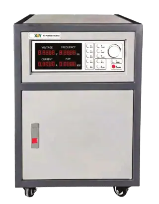
Power Supplies
AC301SHP / AC303SHP Series High-Power AC Grid Simulator Power Supply
XGY AC301SHP / AC303SHP is a high-power programmable AC grid simulator and power supply series for industrial testing, EV motor and charger validation, large appliance testing, and facility-level power simulation.
View productFAQ
Frequently asked questions
How is a regenerative AC/DC source different from a programmable AC source?
A regenerative AC/DC source is selected when the bench must both apply controlled AC or DC conditions and handle returned energy from the DUT. A conventional source may cover steady-state supply simulation, but it may not safely absorb inverter, charger, battery, or DC-bus energy during regenerative or fault cases.
What information is needed for grid-simulation scoping?
The buyer should provide nominal voltage, phase arrangement, frequency range, dips, interruptions, harmonic content, unbalance, recovery behavior, test duration, DUT power level, and fault-response expectations. A phrase like "grid simulator" is not enough because waveform and protection details drive the system design.
Why does facility review matter before quotation?
Facility review matters because regenerative operation, grounding, breaker coordination, cooling, acoustic limits, emergency stop behavior, and reset authority affect the final system. At higher power, the site becomes part of the test bench, not just the place where the equipment is installed.
What should commissioning prove after installation?
Commissioning should prove local power compatibility, safety hardware, emergency stop behavior, source/sink profiles, fault cases, data export, operator handover, and any facility-specific limits. Factory acceptance can prove the supplier scope; commissioning proves the system works in the buyer's real environment.
What should be defined before choosing a bidirectional DC supply?
Define the DC voltage and current windows, continuous and peak power, charge/discharge profile, regenerative sink behaviour, DUT contactor logic, thermal limits, profile duration, and required abort states. A supply rating alone does not prove that the complete bench can handle the DUT safely.
Which fault cases belong in regenerative-bench acceptance?
The project-specific matrix should consider over-voltage, over-current, over-temperature, contactor opening, communications loss, emergency stop, profile abort, facility rejection of returned energy, and verified safe discharge. The expected state and retained evidence for each applicable case should be agreed before FAT.
Keep exploring
Related technical resources
Related articles

Technical Article
Bidirectional DC Power Supply Selection for Battery Cycling
How to evaluate bidirectional DC power supplies for battery cycling, inverter validation, regenerative load testing, and EV bench workflows.
Read article
Procurement Checklist
Battery Test System Quote Requirements for Engineering Buyers
What to include in a battery test system quote request, including voltage, current, regenerative operation, safety states, reporting, and acceptance evidence.
Read article
Technical Article
Automated Test Rack Acceptance Plan for Australian-Made Systems
How to define acceptance criteria for Australian-made automated test racks, including measurements, safety, reports, FAT/SAT evidence, and export review.
Read article