
In brief
Select an RF signal generator from the stimulus required at the receiver input, including frequency, level, phase noise, modulation or pulse behavior, switching, timing, and automation. Upper frequency coverage alone is insufficient when path loss, signal purity, or integration determines the result.
Key takeaways
- Define receiver bands, input levels, sensitivity and interferer cases, modulation, pulse behavior, and the calibrated cable or fixture loss to the DUT plane.
- Match phase noise, level repeatability, switching speed, waveform support, triggers, and reference clocks to the actual receiver method rather than a generic source specification.
- Acceptance should verify stimulus at the receiver plane, automated sequencing, known-good and fail behavior, error handling, and a traceable report.
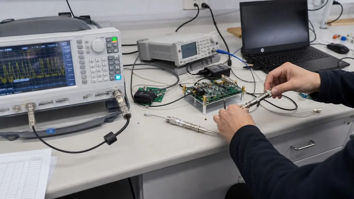
Receiver testing is a controlled comparison between a known stimulus and a defined receiver response. The signal generator is suitable only if it can create that stimulus at the receiver’s reference plane with sufficient purity, timing, repeatability, and evidence. A front-panel frequency and power readback are commands; they are not proof of what reached the DUT after cables, switches, attenuators, fixtures, couplers, and mismatch.
Start with the receiver method, not the source catalogue. Identify the applicable technology, release or standard edition, band, channel bandwidth, reference sensitivity or blocking test, modulation, resource allocation, coding, packet/frame structure, and receiver verdict. The 3GPP 38-series index, for example, separates UE, base-station, physical-layer, measurement, and conformance specifications. “5G receiver test” is not one waveform or one limit.
Define the receiver verdict before the RF stimulus
A sensitivity test needs a response metric: bit-error ratio, packet-error ratio, throughput, detection probability, demodulation result, audio criterion, alarm state, or another method-defined quantity. It also needs an observation interval, traffic/data pattern, confidence or repeat rule, and threshold. Without these fields, the team may tune source level until a receiver “seems to work,” producing a result that cannot be repeated.
Separate common test families:
- sensitivity: wanted signal is reduced until a defined receiver criterion is reached;
- blocking/desensitisation: wanted signal is held while a strong out-of-band or offset signal is applied;
- adjacent-channel/selectivity: wanted and unwanted modulated signals are combined with controlled frequency and level relationships;
- intermodulation: multiple sources create a specified frequency relationship at the receiver plane;
- pulse/radar detection: pulse width, repetition, rise/fall, amplitude, timing, and detection criterion are controlled;
- production screen: a reduced set of known-good, forced-margin, and fail cases verifies assembly and calibration within takt time.
Each family drives different source purity, switching, synchronisation, combining, and verification requirements. One high-frequency source may cover sensitivity but be unsuitable as a close-in blocker because of phase noise or residual modulation.
Establish the receiver-plane power equation
For a simple single-path setup in dB units:
P_DUT = P_source - L_cable - L_switch - L_attenuator - L_fixture + G_active
All terms are evaluated at the same frequency and state. Losses are positive quantities subtracted from source output; calibrated active gain is added. If a correction table is defined as signed correction rather than loss, the software equation must reflect that convention. Store the measurement plane, route, frequency, temperature condition, and correction revision with every result.
For multi-source tests, add isolation and interaction requirements. A combiner can couple one generator into another; source reverse-power limits and protection matter. Attenuators can improve match and isolation but consume level. Switch paths can have state-dependent loss and repeatability. The path should be characterised in the exact route used, not represented by one nominal cable-loss value across all bands.
Remote source levelling or a power-sensor verification step can help, but it does not remove mismatch between the verification plane and DUT connector. Define whether the receiver-plane level is established by direct measurement, characterised path correction, closed-loop levelling, substitution, or a combination. The method must also say how often the path is reverified and what drift triggers a hold.
Build an uncertainty budget that matches the decision
Potential level-uncertainty components include source level calibration, attenuator calibration, switch/cable/fixture correction, connector repeatability, mismatch, drift, temperature, power-sensor calibration, linearity, path interpolation, and repeat connection. Some components are correlated and should not automatically be combined by root-sum-of-squares.
For a simplified fictional model with independent standard uncertainty components expressed in dB, a screening combination is u_c = sqrt(u_1^2 + u_2^2 + ... + u_n^2). NIST Technical Note 1297 provides the underlying discipline: define the measurand, identify Type A and Type B components, handle correlations where relevant, combine them appropriately, and report the coverage treatment. The actual receiver-plane budget must follow the real path and method.
Set a test-system accuracy ratio or guard-band policy only after the method tolerance and attainable uncertainty are known. If the difference between a passing and failing stimulus is comparable with expanded uncertainty, more display digits do not resolve the decision. A pre-agreed inconclusive/retest state is more defensible than repeatedly testing until a pass appears.
ISO/IEC 17025 is relevant where laboratory competence or accredited results are required. It encompasses method control, traceability, equipment, environment, personnel, records, and valid results. A signal generator with a calibration certificate does not make the integrated receiver method accredited.
Decide when phase noise and residuals dominate
Phase noise describes random phase fluctuations around a carrier as a function of offset frequency and measurement conditions. It matters when the source’s noise sidebands mix with strong signals or occupy the same offset region as the receiver behaviour being assessed. Close-in blocking, reciprocal mixing, narrowband receivers, radar, frequency synthesis, and adjacent-channel work can be source-purity limited even when nominal carrier frequency and level are correct.
Specify carrier frequency, offset frequencies, level, modulation state, reference-clock condition, and required phase-noise boundary. A single value at one offset cannot describe the entire profile. Residual AM, harmonics, spurious outputs, broadband noise, and subharmonics may also matter. NIST’s phase and amplitude noise metrology programme demonstrates that spectral-purity measurement is a specialised metrology task; do not treat an unverified analyzer screenshot as a source guarantee.
Run a source-substitution or residual test when feasible. If receiver performance changes materially between two sources that both meet nominal frequency and level, investigate phase noise, spurious content, modulation quality, levelling, or timing before attributing the result to the receiver.
Specify modulation, waveform, and pulse integrity
For digitally modulated signals, define standard/release, waveform file and checksum, sample rate, occupied bandwidth, resource configuration, filter, crest factor, peak-to-average behaviour, and level definition. Average power alone can hide clipping. The source, arbitrary waveform generator, amplifier, and attenuator path must preserve peaks without compression.
For pulse work, define pulse width, repetition interval/frequency, rise/fall definition, overshoot, droop, on/off ratio, trigger delay, jitter, burst count, and reference plane. Verify with measurement bandwidth and sampling appropriate to the edge and pulse. A source’s minimum programmed pulse width is not proof of pulse fidelity at the DUT plane.
External IQ, triggers, 10 MHz references, and shared PXIe clocks can align instruments, but the system needs an explicit master clock, lock-status check, startup order, and behaviour on loss of lock. A locked indicator should be captured in logs when timing or phase coherence affects the verdict.
Engineer automation as a measurement process
SCPI provides a common, hardware-independent command language, but command compatibility does not guarantee identical instrument behaviour. Automation should identify the model/firmware, reset or known-state sequence, error queue handling, operation-complete strategy, trigger model, timeout, range state, and file/configuration version.
Avoid fixed delays where status polling or hardware triggers are required. After every critical configuration, query or independently verify the state that determines the measurement. Capture source errors; an empty report after a timeout must not become a pass. In a multi-source blocking test, interlock output enabling so an incorrect route cannot overdrive the receiver.
A production sequence should include a known-good reference or check standard, a forced-margin or known-fail condition, barcode/DUT identity, fixture state, path correction version, calibration validity, software version, operator/station ID, raw result, and final decision. Takt time includes switching, settling, receiver observation, error recovery, and reporting—not only source frequency-switch time.
Illustrative worked example — not a customer case
Assume a fictional sensitivity path. The source is set to -90.0 dBm, a programmed step attenuator contributes 20.0 dB loss, and cable/switch/fixture correction contributes 2.3 dB loss at the test frequency. The estimated receiver-plane level is -90.0 - 20.0 - 2.3 = -112.3 dBm.
For illustration only, suppose the independent standard uncertainty components are 0.40 dB for source level, 0.20 dB for the attenuator, and 0.30 dB for the remaining path. The screening combined standard uncertainty is about 0.54 dB (sqrt(0.40^2 + 0.20^2 + 0.30^2)). This is incomplete unless mismatch, connector repeatability, drift, interpolation, temperature, and correlations are demonstrably negligible or included.
The receiver method sets a fictional criterion at this level. Rather than reporting a sensitivity of -112.3 dBm with false precision, the team brackets the transition using a defined step, observation interval, and repeat rule; retains all outcomes; and applies its documented uncertainty/decision policy. The values are not an XGY source rating, a standards limit, or a real receiver result.
Receiver-source acceptance matrix
| Acceptance area | Evidence required | Reject or hold when |
|---|---|---|
| Frequency and level plane | Direct check or characterised correction at each route/band, source state, and DUT connector | Front-panel level is treated as receiver level with unknown path loss |
| Receiver verdict | Defined metric, threshold, observation interval, repeat/confidence rule, and retest policy | “Receiver worked” is the only pass criterion |
| Source purity | Phase-noise profile at relevant offsets, residuals/spurs, modulation quality, and source-substitution evidence where needed | Nominal frequency coverage is used to approve a purity-sensitive test |
| Waveform/pulse | File/checksum, sample rate, bandwidth, crest factor, pulse parameters, trigger/reference state, and verification | Programmed waveform is accepted without DUT-plane integrity evidence |
| Automation | Known-state sequence, command/error log, trigger flow, timeout handling, correction version, and forced fail | An instrument error, unlock, or timeout can be converted into a pass |
| Traceability | DUT ID, source/route IDs, calibration status, settings, software/firmware, raw data, uncertainty, and verdict | The stimulus that produced the receiver decision cannot be reconstructed |
Product-role boundary
Within approved XGY product content, YSG-P400 is the portable starting point covering a listed 200 MHz–40 GHz range for field, service, and flexible bench work. YSG-400B is the benchtop starting point, with model-dependent listings of 9 kHz–20 GHz or 40 GHz, -120 dBm to +17 dBm output, and -110 dBc/Hz phase noise at 10 kHz offset from a 10 GHz carrier under the published condition. PXIe microwave sources are supplied to order against the chassis and slot plan.
These figures must remain attached to their named models and stated conditions. They do not establish level accuracy at the receiver plane, modulation support, switching time, phase-noise performance at other carrier/offset conditions, or suitability for a specific 3GPP, IEEE, radar, satellite, or production method. The portable, benchtop, and PXIe roles should be selected from workflow, timing, integration, and evidence needs after the stimulus is defined.
Common failure modes
- Source selection stops after frequency coverage, ignoring level range, purity, or waveform.
- Path loss is measured once, then cables, switches, adapters, or temperature change.
- A blocking source couples into the wanted-signal source and creates an unrecognised path.
- Average waveform power is correct while crest-factor clipping corrupts modulation.
- Phase noise is quoted at a convenient offset unrelated to the receiver mechanism.
- Fixed software sleeps replace trigger/state verification and create intermittent races.
- The threshold search repeats only failures until a pass appears, without a defined retest rule.
- Calibration certificates are retained, but the integrated receiver-plane uncertainty is absent.
Source-to-claim map
| Claim area | Primary-source basis | Boundary retained |
|---|---|---|
| NR receiver requirements and conformance are specification- and release-specific | 3GPP 38-series and TS 38.104 records | No generic “5G compliant” source or test claim is made |
| WLAN receiver stimuli depend on the applicable MAC/PHY standard | IEEE 802.11-2024 record | No clause-level WLAN conformity is asserted |
| SCPI is a common command language, not identical instrument behaviour | IVI Foundation SCPI source | Automation still controls model, state, errors, timing, and verification |
| Phase/amplitude noise requires specialised metrology | NIST phase and amplitude noise programme | No unverified product purity is inferred |
| Receiver-plane results require uncertainty and competent methods | NIST TN 1297 and ISO/IEC 17025 | The illustrative RSS value is not an accredited uncertainty budget |
Product fit
Signal-source options for receiver test
The related YSG-P400, YSG-400B, and YSG-140 products provide portable, benchtop, and fixed-frequency reference starting points. Select only after the receiver-plane level, frequency, signal purity, modulation, timing, calibrated path loss, automation, and acceptance evidence are defined.
Signal Generators
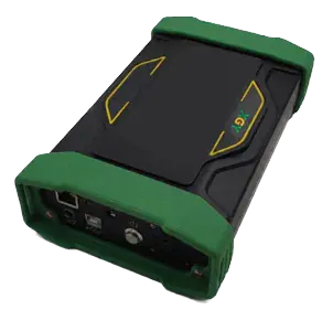
YSG-P400 Series Portable RF Signal Generator
XGY YSG-P400 is a portable RF signal generator covering 200 MHz to 40 GHz with -40 dBm to +10 dBm output, <200 µs switching, OCXO ±0.3 ppm stability, and pulse/AM/FM modulation. It is built for R&D, manufacturing, and field test workflows that need a compact source under 3 kg.
View product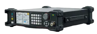
Signal Generators
YSG-400B Series Signal Generator
XGY YSG-400B is a compact RF signal generator for professional test and measurement applications, with 9 kHz to 40 GHz coverage, -120 dBm to +17 dBm output power from 100 kHz to 40 GHz, 0.001 Hz frequency resolution, CW/sweep operation, and standard pulse modulation.
View product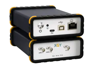
Signal Generators
YSG-140 Low Phase Noise Frequency Source
XGY YSG-140 is a compact low phase noise frequency source for fixed-frequency RF and microwave signal generation. Its RF output frequency is factory-set to a specific value in the 1 GHz to 52 GHz range and is not field-adjustable after production.
View productFAQ
Frequently asked questions
Is upper frequency limit the main signal-generator selection criterion?
It is only the first gate. Receiver testing also depends on output level, phase noise, level accuracy, modulation support, pulse behavior, switching speed, trigger model, reference clock, and the calibrated loss between the source and the receiver input.
When does phase noise become a purchase driver?
Phase noise becomes a purchase driver when receiver sensitivity, adjacent-channel behavior, reciprocal mixing, radar pulse review, or narrowband measurements are limited by source purity. In those cases, a source with the correct frequency range can still be unsuitable if close-in phase noise masks the receiver behavior.
What should be included in a receiver test acceptance run?
A useful acceptance run includes a known-good receiver or reference path, level verification at the DUT plane, modulation or pulse verification, switching sequence, trigger behavior, error handling, and exported report review. The test should prove the stimulus at the receiver connector, not only the source front-panel setting.
When should a PXIe source be chosen over a benchtop source?
A PXIe source is usually the better fit when the station needs shared timing, tight triggering, compact rack integration, automated recipe control, and coordinated measurements with switches, digitizers, VNAs, or safety states. A benchtop source remains practical for flexible lab validation and front-panel troubleshooting.
Keep exploring
Related technical resources
Related articles
Technical Article
Choosing a PXIe VNA for Production RF Test
A buyer-focused guide to choosing PXIe vector network analyzers by frequency range, port count, dynamic range, slot width, and automation workflow.
Read article
Technical Article
Handheld Spectrum Analyzer Checklist for Field RF Troubleshooting
A practical checklist for choosing a handheld spectrum analyzer for interference hunting, 5G checks, EMC pre-compliance, and field RF troubleshooting.
Read article
Procurement Checklist
RF Test Equipment RFQ Checklist for Global Buyers
A practical RFQ checklist for RF test equipment buyers covering frequency range, bandwidth, power, calibration, fixtures, acceptance evidence, and export screening.
Read article