
In brief
Validate a semiconductor test fixture through contact repeatability, electrical and RF paths, thermal conditions, software control, and recorded acceptance evidence. Mechanical fit alone cannot prove that the loaded fixture produces stable, traceable measurements.
Key takeaways
- Scope the device geometry, contact method, SMU or RF range, leakage and guarding needs, thermal state, software output, and operator loading workflow before quotation.
- Repeat loading with open, short, known-device, cable-state, calibration-plane, and thermal-stabilization checks as applicable to the measurement.
- Acceptance should include a known-good case, a forced-fail state, traceable reports, raw evidence, and clear rejection behavior rather than one passing screenshot.
A semiconductor test fixture should be validated by contact repeatability, signal path, thermal condition, software control, and report evidence before it is accepted. The RFQ should include die or package size, pad pitch, probe type, SMU voltage/current range, leakage floor, RF connector type, cable movement limit, temperature range, 1 known-good device, 1 forced-fail state, and the required data fields. A fixture that looks mechanically correct can still fail if a 100 uA leakage test, a 40 GHz RF path, or a 10 um alignment tolerance is not checked under realistic loading.
For XGY Tek, fixture validation is the engineering gate that determines whether components, drawings, probes, cables, instruments, and software form a defensible test workflow. Whether the finished fixture can carry an Australian-made claim is a separate, product-specific origin assessment.
Put the first numerical assumptions in the fixture brief. A useful early note might say “validate 5 V bias, 100 uA leakage limit, 40 GHz RF path, 50 ohm connector path, 10 mm fixture clearance, and 3 repeat loading runs.” Even if those numbers change, they force the fixture review to address electrical path, RF path, mechanical access, and repeatability instead of only checking whether the drawing looks right.
Start with the device and contact method
Semiconductor fixtures are easy to underspecify because the mechanical drawing feels concrete. The drawing is only one part of the requirement. The buyer should state device format, pad or pin geometry, contact force, expected insertion or probe cycles, operating voltage, current range, frequency range, thermal condition, shielding needs, and whether the fixture connects to an SMU, VNA, spectrum analyzer, matrix switch, or custom instrumentation.
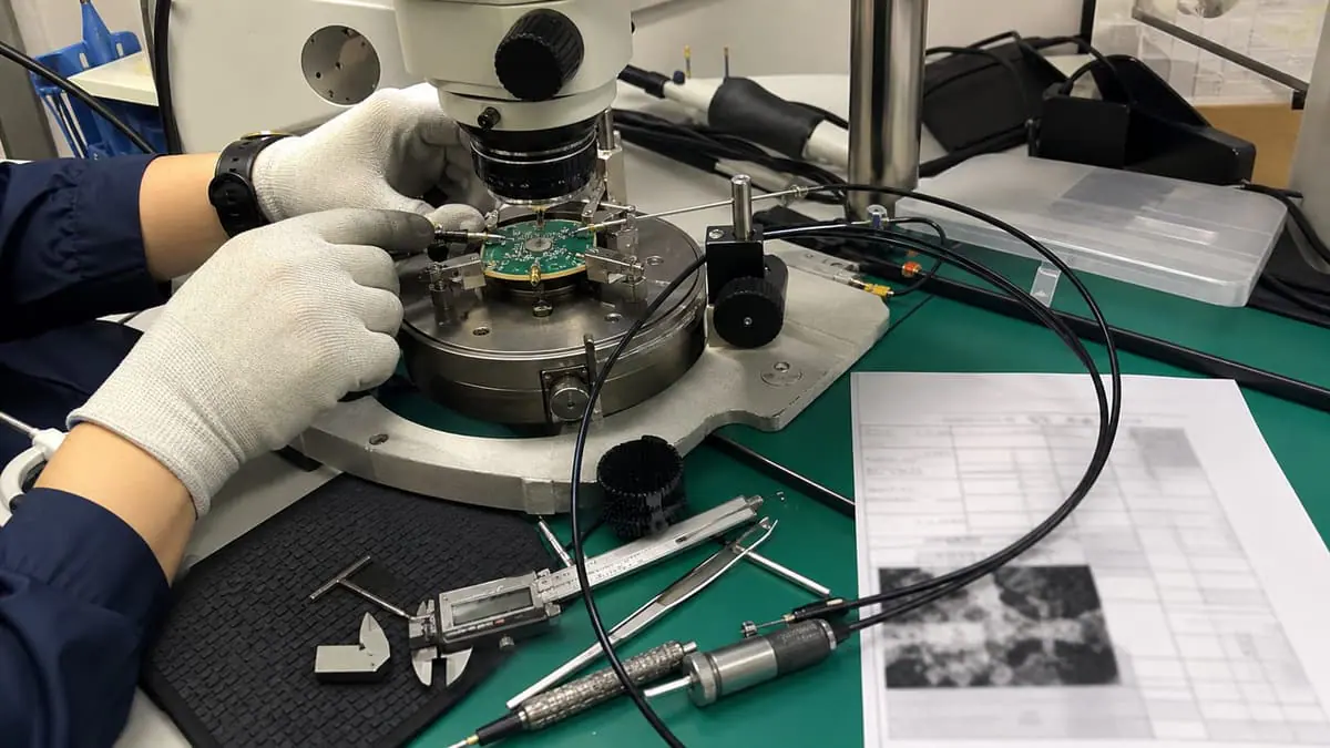
For wafer-level work, include chuck size, probe position, microscope access, thermal chuck range, probe card or manual probe details, and cable strain relief. For packaged devices, include socket type, lid or clamp mechanism, alignment features, operator loading method, and replaceable wear parts.
The fixture should also include software and reporting assumptions. If results go to CSV, PDF, database, or a lab notebook, define the data fields before the fixture is built. Retrofitting traceability after operators start testing is painful.
Engineering Review Matrix
| Validation area | What to inspect | Evidence to request | Failure mode |
|---|---|---|---|
| Mechanical access | DUT size, pad pitch, package body, clamp, alignment, and operator load path | Drawing review, fit check, photos, loading note | Fixture fits one sample but damages or misaligns others |
| Electrical path | SMU range, leakage, guarding, cable length, contact resistance, grounding | Open/short check, known device result, cable map | Good device fails due to fixture leakage or unstable contact |
| RF path | Connector type, cable movement, adapter count, calibration plane, frequency range | Path note, reference measurement, connector inspection | S-parameter or RF power result changes with cable motion |
| Thermal condition | Chuck, chamber, heat sink, airflow, sensor position, soak time | Temperature record, stabilization rule, exception log | Results drift because DUT and fixture are not at the same state |
| Automation | SCPI/LAN/PXIe control, limits, operator prompts, sample ID, report output | Script revision, pass/fail report, forced-fail record | Data is collected but not traceable or rejectable |
| Acceptance | Known-good device, known-fail or forced-fail state, repeat count, signoff | FAT/SAT checklist, raw data, screenshots | Fixture is accepted after a single unrepeatable pass |
The matrix should be reviewed before quotation and again before acceptance. It keeps the discussion grounded in measurable behavior rather than fixture appearance.
Repeatability beats one good screenshot
A fixture acceptance test should include repeat loading. One good result proves the setup can work once. Repeatability proves the operator can use it without a supplier engineer adjusting the alignment each time. For sensitive SMU work, repeatability should include open, short, and known device checks. For RF work, repeatability should include cable state, connector torque where applicable, and the calibration plane.
If the fixture handles low-current measurement, leakage and guarding must be part of validation. If it handles high-speed or RF measurement, connector wear, cable phase stability, and adapter count matter. If it handles temperature, soak time and sensor placement matter. None of these should be left as “operator care” in the handover notes.
For production or qualification use, include a forced-fail state. That can be an out-of-limit resistance, open contact, communication loss, or software limit breach. The report should show a clear reject, not a blank field or a manual comment.
Australian-made engineering scope
Design review, integration planning, validation, documentation, and accountable delivery in Australia can be described precisely when records support them. A broader Australian-made claim requires a separate product-specific assessment under the applicable country-of-origin rules and must not imply local origin for globally sourced probes, sockets, cables, or instruments.
This is useful commercially because global buyers are not only buying metal or connectors. They are buying a validated fixture, a repeatable workflow, and a support path. The origin claim should reinforce that engineering value without drifting into unsupported component-origin claims.
Engineering decision method
Separate four layers before selecting the fixture architecture. The device layer defines geometry, materials, pads or pins, safe operating area, thermal state, and permitted handling. The contact layer defines probe or socket type, force, travel, alignment, cleaning, wear, and replacement. The measurement layer defines stimulus, measurand, range, reference plane, guarding/shielding, switching, cabling, instrument control, and uncertainty. The decision layer defines limits, retest policy, forced failures, records, and authority to release or reject.
For every critical requirement, allocate an owner and verification method. “Leakage below the project limit” needs a defined DUT state, settling time, instrument range, cable and guard configuration, environmental conditions, blank/open behaviour, and decision rule. “RF path to the target frequency” needs a connector family, calibration or reference plane, path configuration, cable state, correction method, and repeatability criterion. Without those fields, suppliers can quote mechanically similar fixtures that do not implement the same measurement.
Use a staged release: drawing review, prototype fit/contact review, engineering validation, and production acceptance where production use is intended. A prototype can be suitable for learning while still being unsuitable for routine release. State which stage the quotation covers.
Quantitative validation logic
Use a measurement model to expose fixture contributions. For a low-current example, the indicated current may contain DUT current plus fixture/cable leakage, offset, and noise. For an RF example, the result may contain DUT response plus connector, adapter, cable, switch, and calibration-residual effects. The exact model depends on the method, but writing it down prevents the fixture from being treated as invisible.
Collect variable data across controlled reloads and retain individual values. Report the range (maximum − minimum) or another pre-agreed repeatability statistic, together with sample count and conditions. Do not convert “three runs showed no obvious issue” into a general production capability claim. Production or qualification decisions may require more devices, operators, fixture revisions, contact replacements, and thermal states, selected through the buyer’s risk and quality process.
NIST explains that traceability belongs to a measurement result produced through a documented calibration chain and measurement system; a calibrated SMU or VNA alone is insufficient. The JCGM GUM provides the general uncertainty framework. Where uncertainty influences conformity, the plan should identify significant contributions and state the decision rule before results are seen. No universal guard band or test-uncertainty ratio is imposed by this checklist.
Evidence package and rejection triggers
The controlled package should contain the DUT drawing and revision, contact map, fixture drawings, socket/probe/contact part numbers, cable and adapter list, I/O and interlock map, instrument and software configuration, measurement method, calibration/reference-plane procedure, cleaning and inspection instructions, wear-part limits, acceptance protocol, raw results, report output, deviation log, and service/revalidation procedure.
Reject or reopen acceptance when contact lands outside the approved region, a DUT can be inserted in the wrong orientation, cable movement changes a result beyond the project criterion, blank or open behaviour exceeds the defined baseline, thermal equilibrium is not demonstrated where required, an interlock can be bypassed through normal operation, a forced-fail becomes blank or pass, or a report cannot be tied to the DUT, fixture, software, limits, and instruments used.
Define change triggers. A revised die pad, package finish, socket, probe, coaxial jumper, adapter, clamp force, thermal interface, guard connection, correction file, script, or limit table can invalidate evidence. Every result should carry the fixture and method revision needed to decide whether revalidation is required.
Illustrative worked example — not a customer case
Assume a hypothetical fixture measures a packaged device on four guarded DC nodes and one coaxial port. The project—not this article—sets a leakage limit, a 3 GHz RF endpoint, a controlled room-temperature state, five independent reloads, one lifted-contact failure, and one machine-readable report per run. The team first records a blank fixture result, then a known reference device, then the DUT sequence.
The first prototype fits mechanically, but the blank result changes materially when the lid closes. Investigation finds that the guard connection is strained by the closing motion. The fixture is not accepted on the strength of its good fit or one passing DUT. The guard routing is revised, the fixture revision increments, and blank, reference-device, reload, forced-fail, and report checks are repeated. The final record retains every run and links it to the contact map, cable state, instrument configuration, software version, limit file, and thermal condition.
This example is invented for explanation. It is not a real XGY Tek or customer project, a validated design, an accuracy or leakage claim, or evidence that XGY Tek tested such a fixture. Actual values, run counts, safety controls, and standards must be selected from the device, method, risk, and intended use.
References reviewed
The semiconductor-standard, traceability, connector, laboratory, control, uncertainty, safety, and origin contexts were checked against the cited primary sources. The exact standard set and validation depth depend on the device, measurement method, market, customer quality system, and intended use. The governing rule remains: validate the complete physical and measurement path, not only the machined assembly.
Product fit
XGY Tek options for semiconductor fixture validation
The related probe-station, SMU, RF-accessory, and test-fixture collections identify the equipment families that may form a fixture workflow. Suitability still depends on the device geometry, contact method, measurement and leakage range, RF path, thermal state, loading repeatability, software, and acceptance evidence.
Product family
Probe Stations
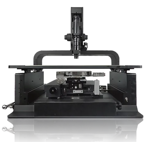
XGY probe stations are scoped for wafer-level DC, RF, thermal, and failure-analysis work where wafer size, chuck temperature, probe count, stage resolution, vibration, shielding, contact repeatability, and data workflow must be reviewed together.
View product
Product family
Source Measure Units
XGY offers three model-specific PXIe source measure units: XMU-5422 and XMU-5421 for precision four-channel characterization, and XMU-5921 for synchronized 32-channel workflows.
View product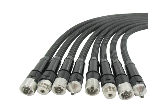
Product family
RF Accessories
XGY RF accessories span the VT, PT, and GL cable series from DC to 110 GHz, XDA active directional antennas from 500 MHz to 20 GHz for YSA-P400 field work, EM5040 LISNs, adapters, and attenuators, chosen on insertion loss, return loss, phase movement under flex, shielding, and calibration traceability.
View product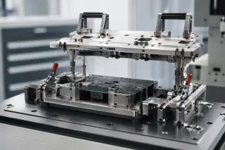
Product family
Test Fixtures
Custom test fixtures scoped around DUT geometry, contact method, RF or power path, safety interlocks, operator workflow, cycle life, and acceptance evidence.
View productFAQ
Frequently asked questions
What should be in a semiconductor fixture RFQ?
Include device format, pad or pin geometry, probe or socket type, SMU range, leakage target, RF frequency range if relevant, thermal condition, cycle expectation, software output, destination, and acceptance evidence.
How many repeat runs are enough?
For early engineering, 3 repeat load/unload runs can expose obvious contact or operator issues. For production or qualification, define repeat count, sample mix, tolerance, and rejection criteria with the buyer quality team.
What is a common fixture validation gap?
A common gap is accepting the fixture after one passing measurement without checking forced-fail behavior, report traceability, contact repeatability, cable movement, or thermal stabilization.
Can fixture validation support Australian-made wording?
Fixture-validation records can support a factual description of work performed in Australia, but they do not by themselves establish an Australian-made claim. Use that wording only after a product-specific origin assessment supports the applicable country-of-origin test and the overall impression.
Keep exploring
Related technical resources
Related articles
Technical Article
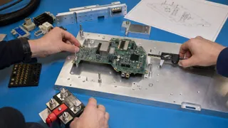
Custom Test Fixture Scoping Before Quotation
What engineering teams should provide before requesting a custom RF, power, semiconductor, or electronics test fixture quote.
Read article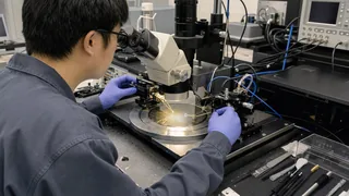
Technical Article
Manual Probe Station Checklist for Wafer-Level Test
What to check before buying a manual probe station for semiconductor wafer, RF probe, and device characterization workflows.
Read article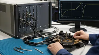
Technical Article
Source Measure Unit Selection for Semiconductor Test
A practical guide to selecting source measure units for semiconductor characterization, wafer probing, production validation, and automated test.
Read article