
In brief
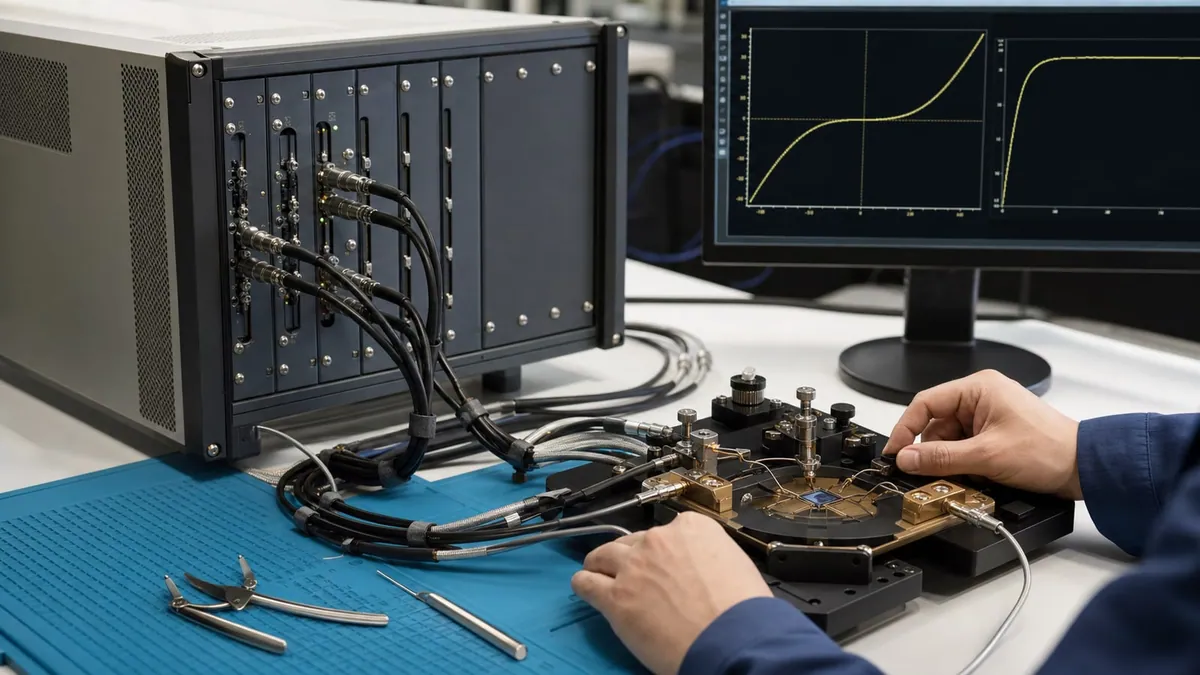
Select a source measure unit from the DUT pin map and complete test workflow: voltage and current range, resolution, channel count, guarding, sweep timing, compliance, integration, and reporting. Raw precision alone is not enough if the fixture, synchronization, protection, or data path cannot support the measurement.
Key takeaways
- Define voltage, current, expected leakage, compliance, resolution, settling, sweep or pulse behavior, and protection for every stimulated or measured DUT pin.
- Choose high-sensitivity single or dual channels for guarded low-current or higher-voltage work, and dense multi-channel architecture when simultaneous moderate-voltage bias count is the main requirement.
- Validate the SMU with the real fixture and environment, including open and short states, compliance recovery, timing, channel mapping, aborted sweeps, and traceable data export.
An SMU should be selected from a complete source-measure-protect sequence, not the largest voltage range or smallest displayed current. The decisive evidence is whether the configured channel can bias the DUT in the required quadrant, enforce a safe compliance limit, settle within the test time, resolve the measurand above fixture leakage and noise, coordinate with other channels, and report uncertainty and status without hiding compliance or range changes.
Translate the DUT method into a four-quadrant envelope
For every pin, tabulate normal and fault voltage, sourced or sunk current, polarity, dwell, sweep direction, pulse width and duty cycle, compliance, expected device response, contact type, and safe shutdown state. Mark whether the channel must source power, absorb power, or alternate between them. “Four-quadrant” describes combinations of voltage and current polarity; it does not mean every voltage-current pair is continuously available. The safe operating area, per-range limits, pulse limits, thermal derating, and module cooling still govern.
Compliance is a protection boundary and a measurement state. In voltage-source mode, current compliance limits current; in current-source mode, voltage compliance limits voltage. A point taken while compliance is active does not represent the programmed stimulus, so software must store the compliance flag and normally invalidate or separately classify that point. Define recovery after compliance, not just the limit value.
For destructive breakdown or high-field characterization, distinguish the intended endpoint from an uncontrolled fault. Specify maximum charge and energy, abort latency, current limit, external protection, interlock, and what happens if the software or communication path fails. Approximate delivered electrical energy with E = integral V(t) I(t) dt; a rectangular estimate E approximately V I Delta t is only a screening calculation because current, voltage, cable storage, and DUT behaviour can change during the event.
Separate range, resolution, accuracy, noise, and sensitivity
These terms answer different questions. Range is the allowed operating interval. Resolution is the smallest display or code increment. Accuracy is closeness under stated conditions and usually includes terms such as gain, offset, temperature, and elapsed time. Noise describes random variation over a bandwidth and integration time. Sensitivity is the smallest change that can be usefully detected by a defined method. A statement about the smallest current increment must not be rewritten as an accuracy claim.
Choose the source and measure ranges around the real operating points, including transients. Autoranging can extend coverage but introduce timing discontinuities, charge injection, relay wear, or gaps in a sweep. A fixed range may improve determinism but saturate on faults. Acceptance should exercise every planned range transition and verify that reported range metadata matches the acquired point.
Use remote sense when lead and contact resistance would create meaningful voltage error. With two-wire forcing, DUT voltage is approximately V_DUT = V_source - I(R_force+ + R_force-). Four-wire Kelvin sensing moves the voltage measurement closer to the DUT, but it does not remove probe contact instability, thermoelectric offsets, common-mode constraints, oscillation risk, or current-path heating. The sense leads also need open-lead detection and safe routing.
Model settling before promising sweep speed
The source, cable, fixture, switch, probe, and DUT form a dynamic circuit. For a first-order RC response, the remaining fraction after time t is epsilon = exp(-t/RC), so t = -RC ln(epsilon). Reaching 0.1% of final value in this ideal model takes about 6.9RC. Real semiconductor devices may add dielectric absorption, traps, junction charging, thermal drift, instrument filtering, range changes, and feedback settling; the RC relation is a starting estimate, not a universal delay.
Define source delay, aperture or integration time, filter, trigger point, samples per point, settling criterion, and maximum test time together. For hysteretic devices, record sweep direction and history. For pulsed work, specify rise/fall time at the DUT, overshoot, pulse width, duty cycle, measurement aperture within the pulse, and cable/fixture bandwidth. A programmed pulse is not proof of the waveform delivered at the device plane.
Design low-current integrity outside the instrument
At picoampere and femtoampere scales, the fixture can become the measurand. Build a leakage map covering cable insulation, connectors, relays, probe card, chuck, socket, PCB surface, contamination, humidity, condensation, light, triboelectric cable motion, and dielectric absorption. Run open-fixture and guarded dummy checks through the same path and timing used for the DUT.
Shielding and guarding solve different problems. A shield intercepts electromagnetic interference. A driven guard holds nearby insulation or conductors close to the high-impedance node potential, reducing leakage current through finite resistance; guard stability, voltage limits, geometry, and contamination still matter. Triaxial cabling can carry force/high, guard, and shield, but pin assignments and connector safety must be documented end to end.
Use a measurement model such as I_DUT = I_indicated - I_zero - I_fixture + C_other, where each correction is defined and each residual contribution has an evaluated uncertainty. Do not subtract a single open reading blindly if leakage changes with voltage, polarity, humidity, time, or switch state. NIST’s low-current calibration work demonstrates that traceable small current can be related to voltage and resistance, and its current-to-voltage research reinforces that low-current gain requires calibration. Neither source implies that a fixture is automatically traceable.
Coordinate channels, switches, and protection
Multi-channel semiconductor tests often sweep one terminal while holding others, sequence supplies to avoid parasitic conduction, or capture current concurrently. Define whether “simultaneous” means a common trigger, aligned apertures, or truly synchronous sampling, then specify permissible skew and jitter. Trigger-cable delay may be insignificant for a slow leakage test but decisive for pulsed behaviour.
Switch matrices add leakage, contact potential, capacitance, charge injection, settling, and path-dependent limits. Never hot-switch unless every module and relay path is rated for the voltage, current, energy, and sequence. An apparently open DUT path can retain charge. Define discharge, verify-safe, and relay-state rules before operators can access the fixture.
PXIe integration can support compact multi-instrument timing, but it introduces chassis slot, power, cooling, trigger-route, controller, driver, and recovery dependencies. IVI or SCPI interfaces can improve automation structure, yet actual attribute coverage and error behaviour remain device specific. Pin software, firmware, driver, and calibration versions in the recipe.
| Test need | Architecture priority | Required acceptance evidence |
|---|---|---|
| Guarded gate or sensor leakage | Low-current gain/offset, guarding, stable ranges | Open/short/reference results versus voltage, time, humidity and cable movement |
| High-voltage IV sweep | Voltage envelope, compliance and stored energy control | Range accuracy, ramp/abort behaviour, interlock, discharge and DUT-plane verification |
| Pulsed high current | Pulse safe area, waveform fidelity and contacts | DUT-plane voltage/current waveform, duty cycle, overshoot, thermal and fault tests |
| Multi-terminal bias | Channel count, sequencing, skew and compliance interaction | Pin map, trigger timing, channel-to-channel influence, safe start/stop states |
| Production screening | Deterministic recipe, throughput and records | Known-good/fail samples, repeatability, full cycle distribution, retest lineage |
Calibration, verification, and uncertainty
Define calibration coverage for each used source and measure function, polarity, range, connection mode, and time/temperature condition. A calibration certificate for the module does not include cable, switch, probe, socket, or DUT contact unless those are explicitly within scope. Maintain traceability of reference standards and verify the assembled path with suitable resistors, current references, voltage references, open/short artefacts, or check devices appropriate to the range.
An uncertainty budget should match the reported result. Possible components include source calibration, measure gain and offset, noise, drift, timing, contact resistance, fixture leakage, guard error, thermoelectric voltage, temperature, and data fitting. A threshold voltage extracted by regression has different uncertainty from a directly measured current point. Use the JCGM vocabulary consistently: correction, standard uncertainty, combined uncertainty, coverage factor, and expanded uncertainty should not be interchangeable marketing terms.
Set decision rules before testing. If a leakage limit is 25 pA, an indicated 24.9 pA with several picoamperes of uncertainty does not justify an unqualified pass. Guard bands, inconclusive regions, or risk-based rules should be agreed between engineering and quality. Store the rule version with the result.
Failure modes that should stop acceptance
- Lowest current capability is presented as accuracy or a guaranteed system noise floor.
- The DUT voltage is assumed equal to source setting despite lead/contact drop or compliance.
- Autorange transitions create apparent device steps and are not recorded.
- Open-fixture leakage is measured once at zero volts and applied to every bias and humidity.
- Guard and shield are wired interchangeably or the guard rating is exceeded.
- A sweep reports numbers while compliance is active but drops the compliance flags.
- Pulse energy, overshoot, stored charge, or discharge time is absent from the safety review.
- Multi-channel labels in software do not match the physical pin map.
- Retesting overwrites the first failure or changes recipe settings without audit history.
Illustrative worked example: a leakage decision
This is hypothetical arithmetic, not an XGY instrument result, calibration, or customer measurement. Suppose an SMU indicates 23.0 pA on a DUT at the specified bias. A separately evaluated zero correction is 2.0 pA, giving a corrected result of 21.0 pA. Assume standard-uncertainty components of 0.8 pA repeatability, 1.0 pA zero correction, 0.7 pA residual fixture leakage, and 0.5 pA calibration. If justified as independent, their root-sum-square is about 1.54 pA, and an illustrative k=2 expanded uncertainty is 3.08 pA.
The upper end, 24.08 pA, lies below a hypothetical 25 pA limit. That may support acceptance under a rule using the upper expanded-uncertainty bound. But if leakage is voltage-dependent, terms are correlated, coverage is not established, or the required false-accept risk is different, the conclusion changes. The value of the example is the transparent model, not the numbers.
For settling, suppose the combined cable-plus-DUT capacitance is 2 nF and effective resistance is 50 Mohm. The ideal time constant is 0.1 s and 0.1% settling is about 0.69 s. A 50 ms delay would therefore be indefensible without measured evidence of a different dynamic model. Again, this is illustrative, not a product timing claim.
Source-to-claim map
| Engineering statement in this article | Primary or official basis |
|---|---|
| Low-current generation can be traceably related to electrical standards through an uncertainty model | NIST Ohm’s-law low-current calibration work |
| Current-to-voltage gain requires calibrated characterization | NIST gain-calibration research |
| Electrical traceability sits in an international SI metrology framework | BIPM electrical metrology |
| Semiconductor ratings and test terminology require defined device context | IEC 60747-1 |
| Driver and command structures support automation but require implementation validation | IVI specifications and SCPI overview |
| Corrections and uncertainty contributions require an explicit measurand model | JCGM GUM and VIM |
| Competent test/calibration operation includes controlled methods and records | ISO/IEC 17025:2017 |
XGY product-data boundary
XGY provides model-specific pages for XMU-5422, XMU-5421, and XMU-5921. XMU-5422 and XMU-5421 are four-channel PXIe SMUs; XMU-5921 is a 32-channel PXIe SMU with a current range through 32 mA. Apply each model’s own specifications and do not transfer limits between models.
No SMU selection alone establishes DUT-plane voltage, minimum measurable current, timing skew, pulse energy safety, uncertainty, calibration scope, or production throughput. Those outcomes depend on the selected model/range, fixture, cabling, guarding, chassis, trigger/software configuration, environment, and validated method. A quote should bind every required value to the specific model and stated conditions.
Product fit
SMU configuration requirements
Model-specific pages are available for the four-channel XMU-5422 and XMU-5421 and the 32-channel XMU-5921. Use the category page to compare their specifications, then provide the DUT envelope, channel count, fixture, timing, software, and acceptance requirements for a configured system.
Source Measure Units
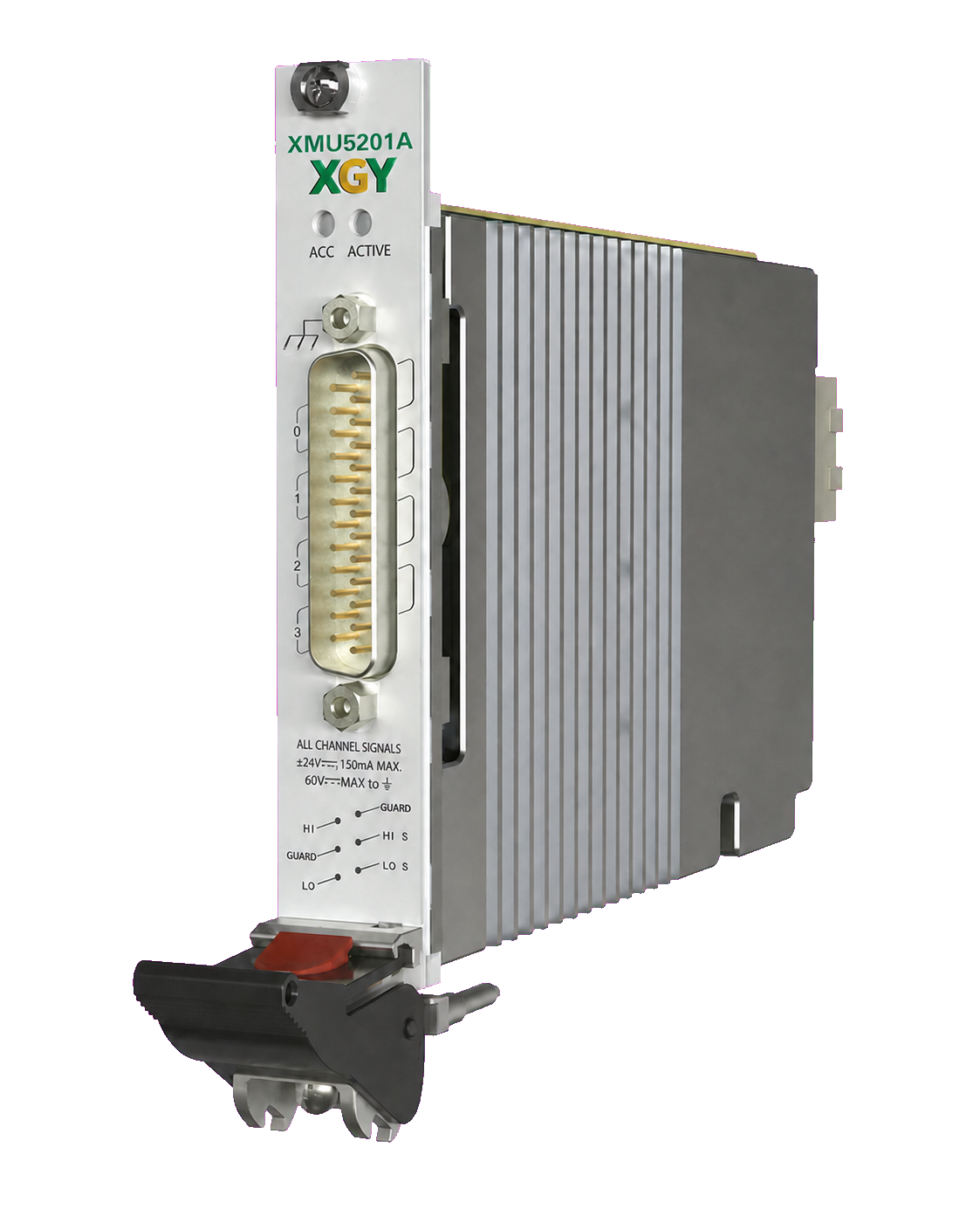
XMU-5422 Four-Channel High-Precision Source Measure Unit
XGY XMU-5422 is a four-channel high-precision PXIe source measure unit for four-quadrant sourcing, measurement, and electronic-load workflows. It combines 600 kSa/s sampling, a ±24 V voltage range, 10 µA / 100 µA / 1 mA / 10 mA / 150 mA current ranges, 20 µV voltage resolution, and current resolution down to 10 pA.
View product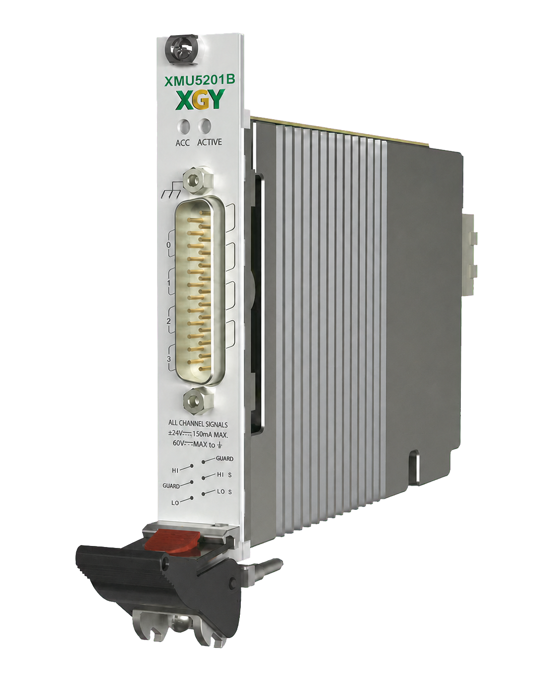
Source Measure Units
XMU-5421 Four-Channel High-Precision Source Measure Unit
XGY XMU-5421 is a four-channel high-precision PXIe source measure unit for four-quadrant sourcing, measurement, and electronic-load workflows. It combines 600 kSa/s sampling, a ±24 V voltage range, 10 µA / 100 µA / 1 mA / 10 mA / 150 mA current ranges, 200 µV voltage resolution, and current resolution down to 100 pA.
View product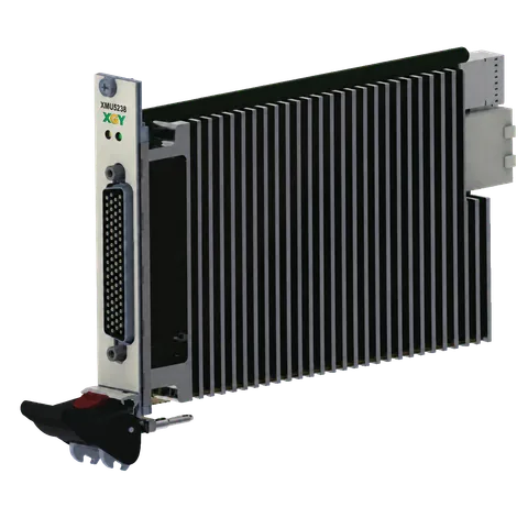
Source Measure Units
XMU-5921 32-Channel Source Measure Unit
XGY XMU-5921 is a 3U PXIe module that integrates 32 synchronized source-and-measure channels for high-density four-quadrant device characterization. It provides 5 V / 10 V / 15 V voltage ranges, 5 µA / 40 µA / 200 µA / 2 mA / 32 mA current ranges, 1 MSa/s sampling, and current resolution down to 80 pA.
View productFAQ
Frequently asked questions
Is SMU selection mainly about voltage and current range?
Voltage and current range are only the first filters. Semiconductor SMU selection also depends on resolution, leakage floor, guarding, compliance behavior, sweep timing, channel synchronization, fixture leakage, cabling, and whether the data must be traceable for release or qualification.
When should a high-precision SMU be chosen over a dense multi-channel SMU?
Choose a lower-channel-count architecture when the DUT requires guarded leakage measurements or tight measurement integrity on a small number of pins. Choose a denser architecture when many pins need simultaneous biasing or compact PXIe integration. Compare every required range, resolution, and accuracy using the model-specific specifications.
What should be included for low-current acceptance?
Low-current acceptance should include open and short checks, guarded measurement setup, cable and fixture leakage review, environmental notes, reference device behavior, repeatability checks, and exported data. Without the fixture and environment, the SMU specification alone does not prove DUT-plane measurement quality.
How should compliance behavior be documented?
The test plan should state source limits, measurement ranges, current or voltage compliance, fault behavior, recovery steps, and whether the DUT can be damaged by an overshoot or wrong range. Compliance behavior matters as much as accuracy when the SMU is protecting semiconductor devices.
Keep exploring
Related technical resources
Related articles
Procurement Checklist
Semiconductor Test Fixture Validation Checklist
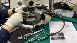
A semiconductor test fixture validation checklist covering probe access, SMU paths, RF cables, thermal conditions, repeatability, reports, and acceptance evidence.
Read article
Technical Article
Manual Probe Station Checklist for Wafer-Level Test
What to check before buying a manual probe station for semiconductor wafer, RF probe, and device characterization workflows.
Read article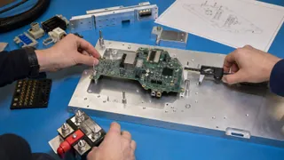
Technical Article
Custom Test Fixture Scoping Before Quotation
What engineering teams should provide before requesting a custom RF, power, semiconductor, or electronics test fixture quote.
Read article