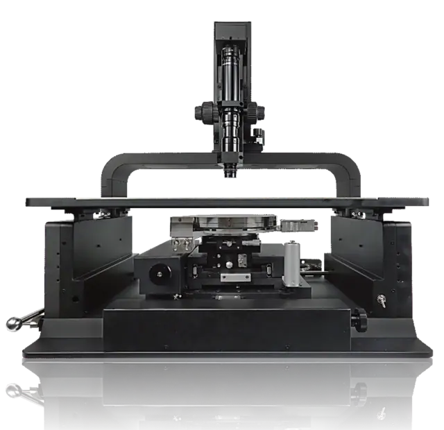
Probe Stations
GPR Series RF Probe
GS and SG RF Probes for On-Wafer Measurements
GPR probes use 3D MEMS micromachining and nickel-alloy tips for on-wafer RF measurements. Four frequency classes cover DC to 26, 40, 50 or 67 GHz, with GS / SG orientation and 50–300 µm pitch options.
Get a Quote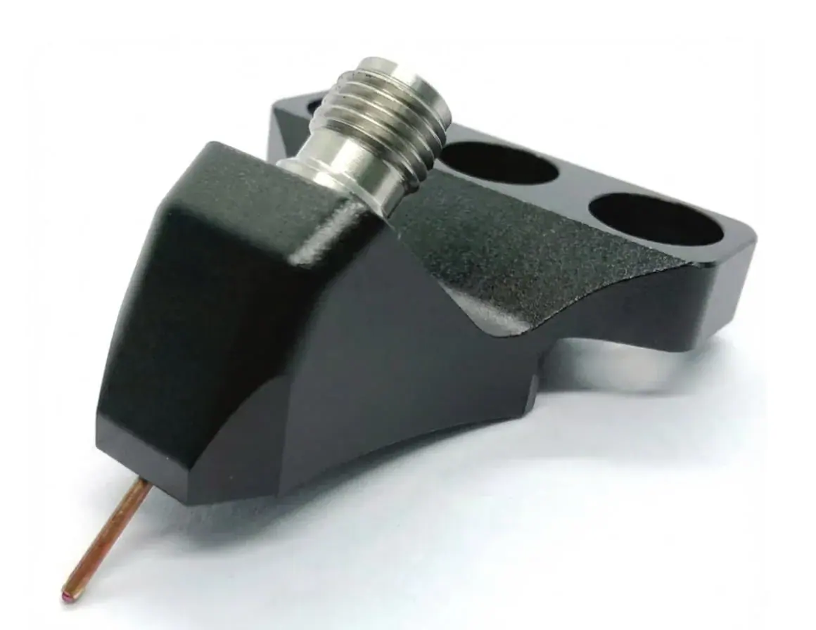
- Frequency range
- DC to 26 / 40 / 50 / 67 GHz
- Configuration
- GS, SG
- Pitch
- 50 to 300 µm
- Impedance
- 50 Ω
Overview
GPR probes use 3D MEMS micromachining and nickel-alloy tips for on-wafer RF measurements. Four frequency classes cover DC to 26, 40, 50 or 67 GHz, with GS / SG orientation and 50–300 µm pitch options.
Additional product details
Available in multiple tip configurations and pitch sizes, GPR Series RF probes are the essential interconnect between your VNA and the device under test. For Probe-to-VNA measurement, a probe cable is listed for compatible GPR probe setups, and the 67 GHz model keeps insertion loss < 1.3 dB at 67 GHz.
Selecting a GPR Probe
Bandwidth is the first decision, and it is not free. GPR insertion loss is specified per model — below 0.9 dB on the 26 GHz probe, 1.1 dB at 40 GHz, 1.2 dB at 50 GHz and 1.3 dB at 67 GHz — so ordering more bandwidth than the device under test requires gives away margin at the frequencies actually being measured. Return loss holds above 14 dB across all four models, and the 50 Ω tip impedance keeps the probe transition consistent with the rest of the measurement path.
Mechanical fit decides the remainder of the specification. GPR pitch follows the pad layout rather than the frequency, and the 50 to 300 µm range covers most on-wafer structures; the proprietary tip design helps reduce probe skating, which is what keeps contact inside a small passivation opening. Nickel alloy tips hold that contact across varied pad metallizations. Confirm the GPR connector interface — SMA, 2.92 mm, 2.4 mm or 1.85 mm — against the existing cable set, and check module compatibility and mechanical constraints against the probe station before ordering.
Key Capabilities & Applications
Frequency-specific probe paths
Insertion loss is <0.9 / 1.1 / 1.2 / 1.3 dB for the 26 / 40 / 50 / 67 GHz models. Return loss is >14 dB across the listed models.
Pad-matched contact geometry
GS or SG orientation, 50–300 µm pitch, 30 µm nickel-alloy tip width and 10–30 µm scrub length define the contact setup.
Calibration and VNA integration
SMA, 2.92 mm, 2.4 mm and 1.85 mm connector options match the frequency class. The universal calibration substrate supports SOLT, TRL and SOLR for GS/SG two-point applications.
Common applications
- On-wafer RF probing
- Probe-to-VNA measurement
- Small passivation opening contact
- Probe-station integration
Applications and test requirements
On-wafer RF probing
Probe-to-VNA measurement
Small passivation opening contact
Probe-station integration
Confirm module compatibility and mechanical constraints during selection.
Technical Specifications
| Parameter | Specification |
|---|---|
| Frequency range | DC to 26 / 40 / 50 / 67 GHz |
| Configuration | GS, SG |
| Pitch | 50 to 300 µm |
| Connector type | SMA / 2.92 mm / 2.4 mm / 1.85 mm |
| Insertion loss | < 0.9 / 1.1 / 1.2 / 1.3 dB for 26 / 40 / 50 / 67 GHz models |
| Return loss | > 14 dB across listed 26 / 40 / 50 / 67 GHz models |
| Impedance | 50 Ω |
| Operating temperature | -60 to +125 °C |
View all 11 specifications
| Parameter | Specification |
|---|---|
| Tip material | Nickel Alloy |
| Tip width | 30 µm |
| Scrub length | 10 to 30 µm |
Detailed performance and interface tables (1)
| Item | Specification |
|---|---|
| Universal calibration substrate frequency | DC to 110 GHz |
| Calibration substrate pitch | 50 to 1000 µm |
| Calibration substrate size / thickness | 15 × 20 mm / 635 µm |
| Calibration methods | SOLT, TRL, SOLR |
| Planarization substrate size / thickness | 20 × 15 mm / 635 µm |
The universal calibration substrate is for GS/SG two-point configurations. GSG or differential four-point layouts require selection from the DUT pad drawing.
Specifications are subject to change without notice.
Models, Configuration & Compatibility
GPR
Model comparison (2)
| Parameter | 26 GHz probe | 40 GHz probe | 50 GHz probe | 67 GHz probe |
|---|---|---|---|---|
| Operating frequency | DC to 26 GHz | DC to 40 GHz | DC to 50 GHz | DC to 67 GHz |
| Connector interface | SMA female | 2.92 mm female | 2.4 mm female | 1.85 mm female |
| Insertion loss | <0.9 dB | <1.1 dB | <1.2 dB | <1.3 dB |
| Return loss | >14 dB | >14 dB | >14 dB | >14 dB |
Electrical values apply across each probe frequency range. The separately illustrated measured samples do not replace these limits.
| Parameter | 40 GHz cable | 50 GHz cable | 67 GHz cable |
|---|---|---|---|
| Compatible probe | 45° connector probe | 45° connector probe | 45° connector probe |
| Probe-end connector | 2.92 mm male | 2.4 mm male | 1.85 mm male |
| VNA-end connector | 2.92 mm female | 2.4 mm female | 1.85 mm female |
| Length | 1.2 m | 1.2 m | 1.2 m |
| Typical insertion loss | 3.50 dB over DC to 40 GHz | 4.49 dB over DC to 50 GHz | 6.48 dB over DC to 67 GHz |
| Typical VSWR | 1.25 over DC to 40 GHz | 1.30 over DC to 50 GHz | 1.35 over DC to 67 GHz |
Accessory cable data is separate from the probe specifications.
Control interfaces and software
Select GS or SG orientation and the pitch to match the DUT pads. The universal calibration substrate supports SOLT, TRL and SOLR for GS/SG two-point applications; waveguide or millimeter-wave setups also require probe-station and mechanical compatibility checks.
GS / SG · SOLT / TRL / SOLR
Order codes and configuration are confirmed in the quotation.
Technical Resources
Selection guidance
Format: GS / SG RF probe
Coverage: DC to 26 / 40 / 50 / 67 GHz; 50 to 300 µm pitch; 50 Ω impedance
Best for: Repeatable on-wafer RF contact for probe-station S-parameter measurement.
Compare products in the Probe Stations categorySend the operating envelope, configuration and acceptance evidence you need; the quotation confirms model, options and delivery documentation.