

Power Supplies
MVGS Series Medium-Voltage Grid Simulator
Direct medium-voltage grid simulation, up to 35 kV by configuration.
A configurable medium-voltage source/load platform for SST, PCS and megawatt-scale power-electronics validation, with four-quadrant regeneration and programmable grid disturbances.
Get a Quote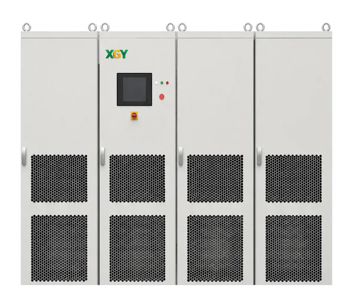
- Output voltage
- Up to 35 kV
- Line-to-line, configurable
- Power capacity
- 1 to 10 MVA
- Standard; expandable to 20 MVA+
- Output THD
- ≤ 1.0%
- At base frequency under linear load
- Power flow
- Four-quadrant
- Regenerative source / load
Overview
MVGS is a four-quadrant medium-voltage grid simulator and programmable AC source/load platform for megawatt-scale power-electronics testing. Its cascaded power-cell topology provides configurable 5 kV to 35 kV output without an external step-up transformer.
Standard power capacity is 1 to 10 MVA, with expansion to 20 MVA and beyond. The selected voltage, power, cooling and interface configuration defines the test-system envelope.
Additional product details
Medium-Voltage Grid Simulation for AI Data Center Power and MW-Scale Power Electronics
The MVGS Series is a medium-voltage grid simulator for projects that need direct 5 kV to 35 kV output, 1 MVA to 20 MVA+ capacity, four-quadrant regenerative operation and programmable grid disturbances in one laboratory platform. It is positioned for AI data center solid-state transformers, energy-storage PCS, high-power renewable-energy systems, and megawatt-scale power-electronics validation.
MVGS is not an AI model or AI software product. It is power-infrastructure validation equipment for teams moving high-power facilities toward medium-voltage distribution, SST conversion stages, energy-storage PCS validation, and grid-interactive renewable-energy systems.
Engineering Use Cases
Typical MVGS projects include AI data center SST validation, SST converter-stage testing, energy-storage PCS source/load validation, renewable-energy inverter and PCS ride-through testing, harmonic and inter-harmonic immunity work, and regenerative laboratory grid emulation. The common thread is that the device under test needs a real medium-voltage electrical boundary rather than a low-voltage approximation.
Validation Workflow
MVGS can support grid-code-oriented workflows such as IEEE 1547, UL 1741, IEC 62116, IEEE 519, and GB/T 19964 test contexts, subject to final configuration and test-plan review. Standard capabilities include LVRT, HVRT, ZVRT, sag, swell, harmonic injection, unbalance simulation, independent three-phase control and programmable RoCoF.
Configuration and RFQ Notes
The modular Power Cell Cascaded topology allows configurable direct medium-voltage output, reducing the need for large external step-up transformers in suitable laboratory setups. Standard control interfaces include LAN, RS485 / Modbus RTU and a fiber optic sync interface; optional analog I/O and RS232 depend on the selected configuration.
For quotation, provide the voltage class, MVA rating, input voltage, output mode, cooling preference, LVRT/HVRT/ZVRT profiles, harmonic order, RoCoF requirement, expected DUT type, site power constraints, protection needs, interface requirements and target acceptance evidence. MVGS is usually not the right starting point for low-voltage benchtop AC source work or projects without a defined safety boundary, cooling plan and FAT/SAT method.
Model Configuration
The series uses a configurable naming structure:
MVGS AAA-BBB-CCC-DDD-EEE
AAA: Rated output powerBBB: Rated output voltage line-to-lineCCC: Rated output currentDDD: OptionsEEE: Input voltage line-to-line
Available options:
-HV: Increased maximum output voltage for HVRT testing-W: Water cooling
Decide Whether MVGS Is the Right Commercial Path
MVGS is the commercial product page for projects that need a real medium-voltage programmable boundary: configurable 5 kV to 35 kV output, megawatt-scale apparent power, four-quadrant source/load operation, and defined disturbance workflows. It should not replace the grid-simulator selection guide, which owns vendor-neutral selection questions, or the medium-voltage grid-simulator RFQ guide, which owns procurement-document structure.
Use a lower-voltage or lower-power platform when the DUT connection, power envelope, event matrix, and facility boundary do not require MVGS. Review the broader power-supply and grid-simulator catalogue before treating medium voltage or MVA-scale capacity as a default requirement.
Evidence Required Before Configuration and Pricing
Send the DUT port voltage and current envelope, required MVA, power-flow directions, output mode, ride-through and disturbance profiles, grounding and protection boundary, cooling preference, facility one-line, interface requirements, and required FAT/SAT files. State which values are mandatory, which are targets, and which remain open for engineering review.
See the MVGS selection guide for family specifications. For SST projects, also review the full-power SST test-bench boundary. Final ratings, event performance, protection, site regeneration, cooling, interfaces, and acceptance evidence remain configuration-specific.
Request an MVGS configuration review with the electrical envelope, facility constraints, and acceptance plan attached.
Engineering Overview
The MVGS Series is a medium-voltage programmable AC power platform developed for grid simulation and megawatt-scale power-electronics validation, including AI data center solid-state transformers, energy-storage PCS systems, and high-power renewable-energy systems. Its modular Power Cell Cascaded topology enables direct medium-voltage output, reducing the need for large external step-up transformers in laboratory environments.
The platform supports both source and sink operation with full four-quadrant regenerative capability. In addition to standard voltage and frequency programming, it can reproduce grid faults, ride-through events, harmonic disturbances, frequency excursions, and three-phase unbalance conditions, making it suitable for grid-code-oriented test workflows subject to final configuration and test-plan review.
Key Capabilities & Applications
Direct medium-voltage testing
Validate SST, PCS, renewable-energy converters and other medium-voltage equipment using configurable output up to 35 kV line-to-line.
Grid disturbances and ride-through
Reproduce LVRT, HVRT, ZVRT, voltage disturbances, unbalance and harmonic injection up to the 50th order. The optional -HV configuration provides 1.3 × rated-voltage overvoltage capability.
Regeneration and system control
Operate as an AC source or regenerative load with energy returned to the grid. Standard LAN, RS485 / Modbus RTU and fiber-optic synchronization support system integration.
All capabilities and operating conditions
Direct Medium Voltage Output
Delivers configurable 5 kV to 35 kV output without bulky external step-up transformers
Megawatt-Scale Expansion
Scales from 1 MVA to 10 MVA standard, expandable to 20 MVA and beyond
Four-Quadrant Regeneration
Operates as both programmable AC source and regenerative AC load with energy returned to the grid
Advanced Grid Simulation
Supports LVRT, HVRT, ZVRT, voltage disturbances, harmonic injection, and unbalance simulation
Project Integration Scope
Standard LAN, RS485 / Modbus RTU, and fiber optic sync interface; confirm additional interfaces for the selected configuration
Common applications
- AI Data Center Power
- Solid-State Transformer
- Medium-Voltage UPS
- PCS / Energy Storage
- Wind Converter
- MV Components
- LVRT, HVRT, and ZVRT ride-through testing
- harmonic and inter-harmonic immunity testing
- MW-scale laboratory grid emulation
Applications and test requirements
AI Data Center Power
Validate MV distribution, SST conversion stages, MV UPS behaviour and PCS interaction before high-power rollout.
5-35 kV · 1-20 MVA+ · Regenerative
Solid-State Transformer
Exercise medium-voltage conversion stages under ride-through events, unbalance and programmable frequency changes.
HVRT · LVRT · RoCoF > 5 Hz/s
Medium-Voltage UPS
Reproduce sag, swell, interruption and dynamic load workflows where a low-voltage source would not represent the system boundary.
< 1 ms rise/fall · 3-phase · MV load cases
PCS / Energy Storage
Run four-quadrant source and sink tests for PCS platforms, regenerative loading and grid-code-oriented disturbance profiles.
AC/DC modes · 50th harmonic · Energy return
Wind Converter
Check converter behaviour during medium-voltage grid events, harmonic conditions and independent three-phase control scenarios.
Unbalance · Phase control · 30-70 Hz
MV Components
Scope reactors, capacitors, resistors, switchgear and other MV components against the configured voltage and protection envelope.
Protection scope · Cooling choice · FAT evidence
Technical Specifications
| Parameter | Specification |
|---|---|
| Output Voltage | Up to 35 kV line-to-line, configurable |
| Power Capacity | 1 MVA to 10 MVA standard, expandable to 20 MVA+ |
| Frequency Range | 30 Hz to 70 Hz standard, custom wide range available |
| Output THD | <= 1.0% at base frequency under linear load |
| Output Modes | AC, DC, AC+DC standard/optional |
| Overvoltage Mode | 1.3 x rated voltageHVRT testing; optional -HV configuration |
| Rise/Fall Time | < 1 ms0% to 90% / 90% to 0% |
| Standard Interfaces | LAN, RS485 / Modbus RTU, fiber optic sync interface |
View all 38 specifications
| Parameter | Specification |
|---|---|
| Product Family | MVGS Series medium-voltage grid simulators / programmable AC power supplies |
| Primary Role | Medium-voltage grid simulation and four-quadrant regenerative AC source/load testing |
| Platform Type | Four-quadrant programmable AC power supply / medium-voltage grid simulator |
| Input Voltage | 10 kV, 13.8 kV, 34.5 kV, or 35 kV AC 3-phase +/-10%, configurable |
| AC Line Frequency | 50 Hz / 60 Hz +/-10%AC input |
| Power Factor | 0.95AC input |
| THDi | <= 3%AC input |
| Efficiency | >= 90% |
| Phase Output Control | 0.0 to 360.0 deg relative phase control |
| Harmonic Generation | Up to the 50th order |
| RoCoF | > 5 Hz/s programmable |
| Voltage Accuracy | <= 0.2% F.S. |
| Current Accuracy | <= 0.3% F.S. |
| Frequency Accuracy | 0.01 Hz |
| Phase Accuracy | +/-0.3 deg50 Hz |
| Cooling | Forced air or liquid coolingLiquid cooling requires optional -W configuration |
| Optional Interfaces | Analog I/O 0 to 5 V / 0 to 10 V for HIL and RS232, depending on configuration |
| Phase setting resolution | 0.1 deg |
| Control display | 15.6-inch industrial TFT touchscreen with Windows-based GUI |
| Waveform capture sampling | Up to 10 kS/s |
| Output load regulation | ≤ 0.2% F.S. |
| Output line regulation | ≤ 0.1% F.S. |
| Measurement power accuracy | ≤ 0.3% F.S. |
| Measurement voltage accuracy | ≤ 0.2% F.S. |
| Measurement current accuracy | ≤ 0.3% F.S. |
| Protection functions | Input OVP/UVP; output OCP/OVP/OPP/OTP/SCP; insulation monitoring; module fault detection |
| Operating environment | 0 to 40 °C |
| Storage environment | -20 to 85 °C |
| Relative humidity | 20 to 90% RH, non-condensing |
| Configuration option codes | -HV: overvoltage capability; -W: liquid coolingOptional configuration codes; project/model dependent. |
Specifications are subject to change without notice.
Models, Configuration & Compatibility
MVGS
Configured electrical envelope
Select the voltage, current and MVA rating for the DUT. The model pattern MVGS AAA-BBB-CCC-DDD-EEE identifies rated output power, output voltage line-to-line, output current, options and input voltage line-to-line.
Voltage and cooling options
-HV provides increased maximum output voltage for HVRT testing, specified as 1.3 × rated voltage. -W specifies water cooling. Both options depend on the selected project configuration.
Control interfaces
LAN, RS485 / Modbus RTU and fiber-optic synchronization are standard. Analog I/O at 0–5 V / 0–10 V for HIL and RS232 are optional, depending on configuration.
Engineering review
Confirm event performance, protection and grounding, site regeneration, cooling and FAT/SAT evidence for the selected system. Family limits do not define every project configuration.
Control interfaces and software
MVGS standard interfaces include LAN, RS485 / Modbus RTU, and fibre-optic synchronisation. Optional analog I/O and RS232 are configuration-dependent. Additional command interfaces, HIL integration, host software, logging, and waveform review should be confirmed during project scoping.
LAN · RS485 / Modbus RTU · Fiber optic sync interface · Optional Analog I/O · Optional RS232
Technical Resources
Selection guidance
Format: Medium-voltage grid simulator
Coverage: Up to 35 kV line-to-line; 1 to 10 MVA standard; expandable to 20 MVA+
Best for: Four-quadrant medium-voltage grid simulation for SST, PCS, renewable-energy, and megawatt-scale power-electronics validation.
Compare products in the Power Supplies categoryInformation for your quotation
- DUT voltage/current envelope, required MVA, power-flow directions, input voltage and output mode.
- LVRT/HVRT/ZVRT and disturbance profiles, harmonic order, RoCoF and interface requirements.
- Facility one-line and power constraints, grounding/protection boundary, cooling plan and required FAT/SAT evidence.
Detailed quotation requirements
- Review the voltage class, MVA range, disturbance capability, harmonics and control interfaces before treating MVGS as a grid-code or AI data center power validation platform.
- Where MVGS earns its place: Built for the gap between lab equipment and utility-scale power. MVGS is most useful when the DUT sits at medium voltage and the test team needs programmable grid behaviour, regenerative loading and project evidence in the same bench plan.
- Direct-to-MV workflow: Make the test plan visible before the cabinet is quoted. The stronger MVGS RFQ is not a long shopping list. It is a short engineering model: operating envelope, grid events, acceptance evidence and integration boundary.
- Step 01 — Set the MV envelope. Confirm input feed, output voltage class, MVA range, cooling, protection boundary and installation constraints. Evidence: Voltage / MVA map.
- Step 02 — Program grid events. Define LVRT, HVRT, ZVRT, sag, swell, unbalance, harmonic and RoCoF profiles for the DUT and target workflow. Evidence: Disturbance profile list.
- Step 03 — Capture acceptance data. Align FAT/SAT records, waveform capture, interface logs and configuration files with the evidence required by the buyer. Evidence: Test report package.
- Request: Send MVGS RFQ.
- Fit: Use MVGS when the project has a real medium-voltage boundary.
- Fit: AI data center MV power architecture validation.
- Fit: SST, MV UPS, PCS and wind-converter test benches.
- Fit: Projects needing direct MV output instead of a step-up transformer chain.
- Fit: RFQs that require FAT/SAT records, waveform evidence and configuration traceability.
- Not fit: Low-voltage benchtop AC source work.
- Not fit: Small inverter tests where MV site power is not available.
- Not fit: Projects without a defined safety boundary, cooling plan or acceptance method.
- Not fit: Teams looking for AI software rather than power-infrastructure validation hardware.
- RFQ checklist: Voltage class; MVA rating; Input feed; Output mode; Cooling option; DUT role; Grid-code workflow; LVRT / HVRT / ZVRT profiles; Harmonic order; RoCoF target; Interface needs; Safety boundary.
- RFQ note: For AI data center power, SST or MV UPS projects, also include the intended architecture, load profile, regenerative-energy requirement and the acceptance evidence expected by the buyer.
Scope a medium-voltage grid simulation bench
Send the voltage class, MVA rating, DUT role, grid-event profiles, site power, cooling and interface requirements for quote-stage engineering review.
Related Products & FAQ
Power Supplies
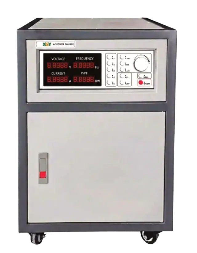
AC301SHP / AC303SHP Series
High-Power AC Grid Simulator Power Supply
Frequency range: 40 to 250 Hz
View detailsPower Supplies
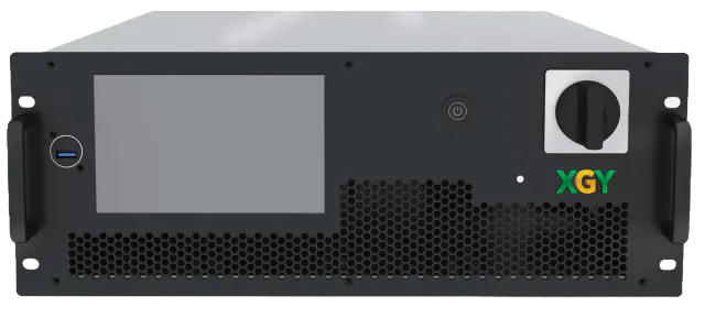
GXC804B-5K Series
Regenerative AC/DC Power Source
Frequency range: DC, 0.01 to 1000 Hz
View detailsPower Supplies
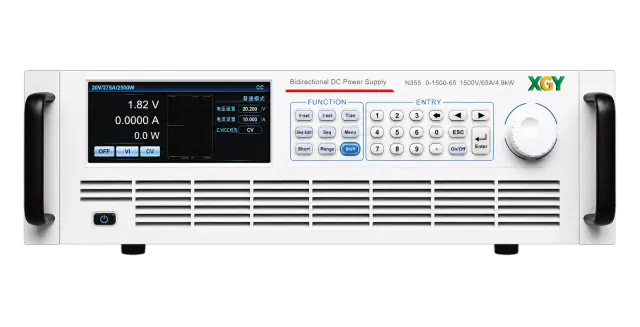
N355
High Power Bidirectional Programmable DC Power Supply
Voltage range: 0 to 2250 V by model
View details