
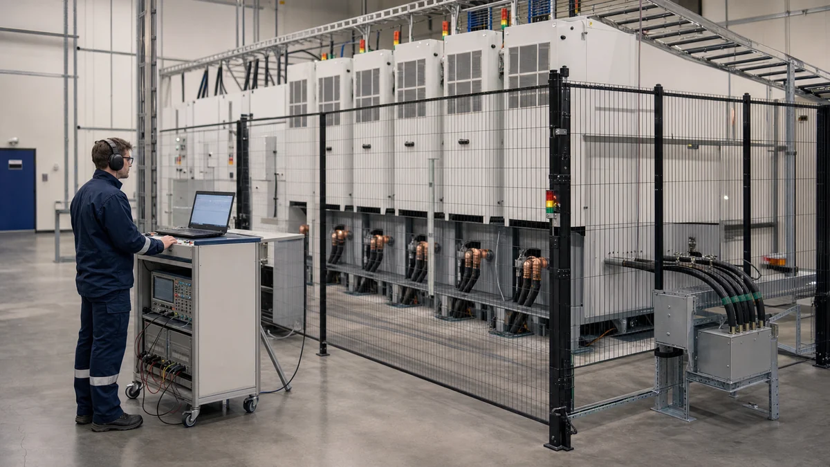
In brief
Ten specifications decide whether a grid simulator fits your programme: voltage class and architecture, apparent-power rating with its overload envelope, quadrant capability, dynamic edge speed, frequency and RoCoF range, per-phase independence, harmonic and inter-harmonic capability, output accuracy with its stated conditions, grounding configurability and protection behaviour, and the automation-and-evidence interface. This guide defines each, explains what it gates, and — most usefully — gives the question that exposes whether a datasheet number is real.
Key takeaways
- Selection is test-plan-driven: every specification below matters only insofar as a row of your test matrix exercises it — start from the matrix, not the brochure.
- The headline numbers are the least informative ones: ratings without durations, accuracies without conditions and edges without load context are marketing, not engineering.
- Architecture is a specification: where isolation sits and how the output is synthesised determines event fidelity in ways no listed parameter captures.
- The unglamorous specifications — grounding configurability, protection behaviour, evidence interfaces — decide more campaigns than the glamorous ones.
- Every question in this guide is fair to ask any vendor, this publication's included; the answers' precision is itself a selection datum.
Before the ten: start from the test matrix
A grid simulator is bought to execute a test plan, and every selection error this series has catalogued traces to inverting that order — choosing hardware, then discovering which tests it can run. So the procedure this guide assumes: write the test matrix first (the device classes, the standards clauses, the event families, per the compliance and application guides), then read the ten specifications below as gates — each one either passes your matrix’s rows or fails them. Two consequences of the procedure are worth internalising before the list. Capability you will not exercise is cost without value: the five-methods guide’s allocation discipline applies to features exactly as to methods, and the honest sections of this knowledge centre exist precisely to say when less machine is the right machine. And capability your matrix requires cannot be negotiated back in later: voltage class, quadrants and architecture are congenital properties — chosen at purchase, lived with for a decade — which is why the ten below are ordered roughly from least changeable to most.
Specifications one to five: the electrical constitution
1 — Voltage class and architecture. The first gate: does the platform reach your device’s real connection voltage, and how? Direct medium-voltage synthesis versus low-voltage-plus-step-up is not a detail but a fidelity decision — the transformer physics of the saturation guide sits inside one architecture and not the other — and where isolation lives (front-end versus output-side) determines grounding freedom and event transparency, per the isolation guide. The exposing question: at my required voltage, what stands between your power stages and my device’s terminals, and what is its measured frequency response?
2 — Apparent power and the overload envelope. Rate in kVA against your device’s full apparent-power envelope — the kW-versus-kVA guide’s arithmetic, including reactive duty and the power-versus-voltage derating curve, because a platform’s rating at nominal voltage says little about its capability at the half-voltage operating points ride-through work visits. Overload capability is only meaningful as a triple: magnitude, duration and current limit. The exposing question: give me the output current-versus-voltage envelope, and the overload figure with its permitted duration and limiting behaviour attached.
3 — Quadrant capability and regeneration. Two-quadrant sources test loads; four-quadrant platforms test citizens — anything that exports, rides through or provides services needs a source that absorbs as well as supplies, per the four-quadrant guide, and where absorbed energy goes (returned to the facility mains versus dissipated) sets campaign economics, per the energy-bill analysis. The exposing question: at full export from my device, where does the power go, at what conversion efficiency, and what does that imply for my facility feed?
4 — Dynamic performance: edges and trajectories. Ride-through fidelity lives in transition speed — sub-millisecond-class edges for code-faithful profiles — and in trajectory control on the way back up, where recovery shapes are specified and misbehaviour hides. Edge specifications are load-dependent claims. The exposing question: show me a measured voltage transition at my full load and my voltage, not the small-signal figure — and state the point-on-wave control available.
5 — Frequency range and RoCoF. The frequency window must cover your codes’ withstand ranges and your special cases (the 30-to-70-hertz class covers most grid work; wider ranges serve aviation and marine adjacency), and RoCoF capability — the programmable ramp-rate ceiling — gates the frequency-event campaigns of the RoCoF guide. The exposing question: maximum sustained ramp rate, over what frequency span, with what waveform continuity through the ramp?
Specifications six to ten: fidelity, safety and evidence
6 — Per-phase independence. Most real faults are asymmetric, so amplitude and angle must be programmable per phase — fine angle resolution, full relative-angle range, and genuine independence rather than shared-magnetics approximation, per the unbalance guide. The exposing question: how is per-phase independence implemented, what cross-coupling exists between phases during asymmetric events, and can the platform hold a single-phase-to-earth condition without tripping?
7 — Harmonic and inter-harmonic injection. Immunity campaigns need a controllable dirty source: individual harmonic components to a stated order with per-component amplitude and phase control, plus inter-harmonics off the integer grid — the capabilities the harmonics guide maps to the immunity standards. The exposing question: to what order, with what per-component control, and what is the delivered spectral accuracy at my load?
8 — Output accuracy, with conditions attached. Voltage accuracy, stability and distortion figures are honest only with their conditions: a THD specification is a linear-load statement unless stated otherwise, and behaviour into your device’s real (distorting, fluctuating) input is the figure that matters. The exposing question: state the measurement conditions behind every accuracy and distortion figure — load type, power level, bandwidth — and show delivered quality into a representative nonlinear load.
9 — Grounding configurability and protection behaviour. The unglamorous pair that decides campaigns: configurable earthing (solid, impedance, isolated) is a prerequisite for ground-fault scenarios and common-mode discipline, per the isolation and common-mode guides; and protection behaviour — what the platform does when your device faults, whether it limits and continues or trips and ends the day, how its protection coordinates with yours — determines whether fault testing is a programme or a series of incidents. The exposing question: walk me through a device-side short circuit at full power — the platform’s limiting behaviour, ride-through of its own, restart procedure, and what evidence the event leaves.
10 — Automation, interfaces and evidence. The capability that compounds: sequence programming with logged execution, control and monitoring interfaces your laboratory can actually integrate (LAN/RS485-class), synchronised capture, durable export formats, and replay of recorded events — the entire toolchain of the sequence, automation and evidence guides, without which an excellent power stage produces excellent anecdotes. The exposing question: show me the sequence a compliance profile becomes, the log it leaves, and the file my certifier receives.
| # | Specification | Gates | Datasheet trap |
|---|---|---|---|
| 1 | Voltage class and architecture | Fidelity at your real boundary | Voltage reached vs voltage synthesised |
| 2 | kVA rating and overload envelope | Your apparent-power and derated operating points | Overload magnitude without duration or current limit |
| 3 | Quadrants and regeneration | Export-capable and ride-through DUTs; campaign economics | "Absorbs power" without stating where it goes |
| 4 | Edge speed and trajectories | Code-faithful ride-through | Small-signal edge quoted, full-load edge unstated |
| 5 | Frequency range and RoCoF | Frequency-event campaigns | Range without ramp-rate ceiling |
| 6 | Per-phase independence | Asymmetric and ground-fault scenarios | Independence claimed, cross-coupling unmeasured |
| 7 | Harmonic/inter-harmonic injection | Immunity campaigns | Order quoted without per-component control |
| 8 | Accuracy with conditions | Measurement credibility | THD without load conditions |
| 9 | Grounding and protection behaviour | Fault campaigns; laboratory uptime | Protection listed, behaviour undescribed |
| 10 | Automation and evidence | Repeatability, throughput, auditability | "Software included" without logs or formats |
What the datasheet cannot tell you
Honesty section, because the ten specifications gate fitness and still do not complete a selection. Engineering support is a specification without a field: megawatt platforms are configured per programme, and the quality of the requirements dialogue — whether the vendor asks about your test matrix, your facility, your grounding scheme before quoting — predicts the project better than any listed number. Safety engineering shows in behaviour, not brochures: interlock philosophy, failure-mode design and the commissioning verification of both, per the automation guide’s boundary. Factory and site acceptance are where specifications become facts: insist on witnessed FAT/SAT with agreed protocols, per the evidence guide, and treat a vendor’s enthusiasm for being measured as the signal it is. And the facility around the machine — feed, cooling, floor, MV practice — is a parallel project the planning guide covers, whose lead times routinely exceed the equipment’s. The selection method, compressed: gate on the ten, decide on the dialogue, verify at FAT.
Product fit
Where the MVGS fits
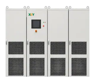
The MVGS answers this guide's ten in the terms the guide demands — conditions attached. A configurable medium-voltage, megawatt-class platform with direct-MV synthesis from front-end isolation; the current sample configuration delivers 5 MVA at 13.8 kV (210 A per phase), four-quadrant with absorbed energy returned to the facility mains, 30–70 Hz with programmable ramps, sub-millisecond-class edges, fully independent three-phase control at 0.1-degree angle resolution, harmonic and inter-harmonic injection with per-component control, configurable earthing with continuity through single-phase grounding events, and sequence, capture and COMTRADE-replay tooling over LAN/RS485. Every exposing question above is welcome at quote stage — with measured answers and their conditions.
FAQ
Frequently asked questions
Which of the ten specifications matters most?
The one your test matrix exercises hardest — which is the point of starting from the matrix. Structurally, though, the congenital trio (voltage class and architecture, apparent-power envelope, quadrants) deserves first scrutiny: they cannot be retrofitted, while automation, and to a degree harmonic capability, can sometimes be extended. Buy the constitution carefully; the toolchain can grow.
How do I compare vendors whose datasheets state things differently?
Normalise with conditions: for every figure, require the load, voltage, power level, duration and measurement bandwidth behind it — the exposing questions in this guide are exactly that normalisation. Comparable answers make a real comparison; a vendor unable to attach conditions to a number has answered a different question, and that too is information.
Is a bigger platform a safer choice?
No — oversizing buys cost, footprint and facility burden without evidence value, and this knowledge centre's honest sections repeatedly mark where less machine is right: kW-class development work, symmetric slow campaigns on characterised step-up chains, two-quadrant duty for pure loads. Size to the matrix's genuine envelope, including its derated operating points, and spend the difference on measurement and automation, which compound.
What should I do with this list next?
Turn it into your RFQ: the ten specifications, each with your matrix-derived requirement and its exposing question, form the technical core of a request that vendors can answer precisely and you can compare honestly — the structure the RFQ guide builds step by step, with the commercial and acceptance sections around it.
Keep exploring
Related technical resources
Related articles
Grid Simulator Fundamentals
What Is a Grid Simulator? A Plain-English Guide
A grid simulator is a programmable AC source that reproduces grid behaviour — sags, swells, harmonics, ride-through events — for lab testing. What it does, who needs one, and how to spec it.
Read article
Application Test Guides
How to Test a Medium-Voltage SST at Full Power
The complete SST test bench, block by block: programmable MV grid interface, regenerative DC load or battery emulator, measurement and safety layer — plus the test matrix and an RFQ checklist.
Read article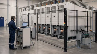
Technical Article
What Is a Solid-State Transformer (SST)? Architecture, Limits, and MVGS Testing
An engineering guide to solid-state transformer architecture, limits, and the role of a medium-voltage grid simulator in full-power SST validation.
Read article