
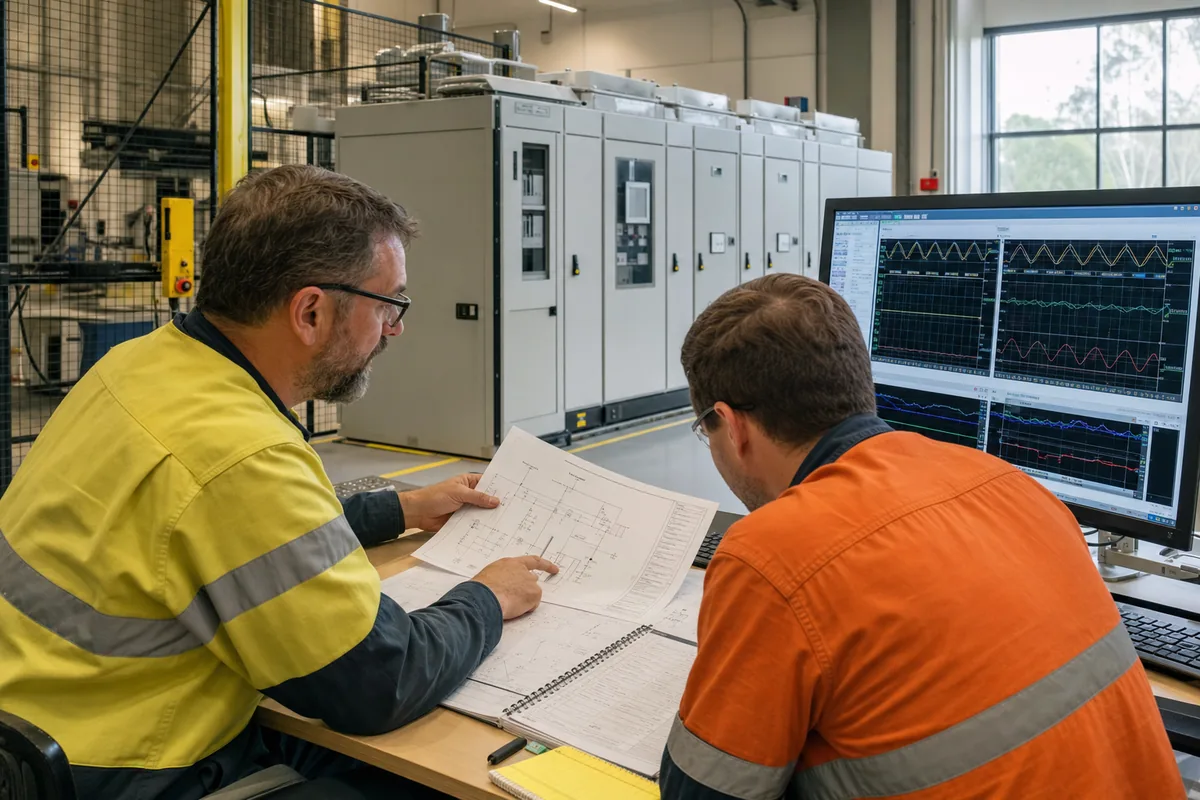
In brief
Full-power SST testing takes a three-block system: a programmable medium-voltage grid simulator on the AC input, a regenerative DC load or battery emulator on the output, and a measurement and safety layer wrapped around both. The grid simulator executes ride-through, harmonic, unbalance and frequency events at the real MV boundary; the DC side absorbs power and replays realistic load profiles; the instrumentation layer turns every event into evidence. This guide assembles the bench block by block and ends with the RFQ checklist.
Key takeaways
- The bench is a chain — facility MV grid, programmable MV grid interface, SST under test, controllable DC side — plus a measurement and safety layer; every block earns its place.
- The input-side test matrix has five families: ride-through, frequency and RoCoF, power quality, unbalance and single-phase events, and grid-support response; each produces a defined evidence artefact.
- The output side must do more than absorb watts: battery emulation and programmed AI-style load transients exercise the control coupling that static load banks never touch.
- Reaching medium voltage through a low-voltage source plus a step-up transformer is workable with known limitations — the transformer joins the test circuit and can filter fast events; direct MV generation can reduce those transformer-related effects.
- A good SST test RFQ specifies the system, not a box: envelope, event list, output-side capability, evidence formats, and facility constraints.
What does the complete test bench look like?
| Bench block | Primary job | Minimum evidence interface |
|---|---|---|
| Facility MV supply | Feeds the circulating-power system and covers conversion losses | Available fault level, protection coordination and utility limits |
| Programmable MV grid interface | Reproduces voltage, frequency, phase, unbalance and power-flow conditions | Commanded profile, measured terminals, timestamps and source status |
| SST under test | Converts power through its MV, isolation and DC stages | Internal state, protection flags, cell telemetry and thermal channels |
| Regenerative DC load or emulator | Absorbs output power and replays load or storage behaviour | DC voltage/current trace, power command and transition timing |
| Measurement and safety layer | Correlates both sides and enforces safe states | Calibrated waveforms, interlock events, trip cause and configuration record |
Read the chain left to right. The facility’s medium-voltage supply feeds the programmable grid interface — a medium-voltage grid simulator — which stands in for every grid the SST will ever meet: nominal conditions, disturbed conditions, and the fault events no utility would permit on purpose. The SST under test sits in the middle with both of its actively controlled boundaries exposed. On the output, a regenerative DC load, battery emulator or DC bus simulator absorbs the power and shapes the conditions the SST’s application will impose — an 800 VDC data-hall bus, a storage system, or both. Because both the simulator and a regenerative DC side return absorbed energy to the facility mains, the bench circulates most of its power rather than burning it, which is what makes long-duration full-power campaigns economically survivable.
The previous article established why both boundaries must be exercised together: the SST’s control system couples them, so input ride-through behaviour depends on output loading and vice versa. The bench above is simply that argument turned into hardware.
What belongs in the input-side test matrix?
Five test families cover the medium-voltage input campaign. The table is the skeleton; the paragraphs after it add the execution detail that separates a plan from a wish list.
| Test family | What it proves | Typical standards context | Evidence artefact |
|---|---|---|---|
| LVRT / HVRT / ZVRT | Stays online and behaves predictably through voltage events | IEEE 1547 / 1547.1; regional grid codes | Waveform captures against the programmed profile |
| Frequency events and RoCoF | Tolerance of frequency excursions and fast ramps | Grid-code frequency requirements | Frequency-trajectory and response records |
| Harmonics and inter-harmonics | Immunity to distorted supply; emission behaviour | IEEE 519 context; IEC immunity practice | Spectrum reports pre/post |
| Unbalance and single-phase events | Behaviour under asymmetry and phase-specific faults, including line-to-PE | Project and code requirements | Per-phase captures and protection logs |
| Grid-support response (P/Q) | Active and reactive power support during and after events | Interconnection performance requirements | P/Q trajectory records |
Execution notes that matter in practice. Ride-through profiles are voltage-versus-time trajectories, so the source must execute programmed curves with millisecond-class edges and hold them precisely — slow edges quietly convert a zero-voltage test into a shallow-sag test. Unbalance and single-phase work requires genuinely independent per-phase control of amplitude and angle; approximating asymmetry with a three-phase dip tests something different. And every family should run as a scripted, repeatable sequence with configuration captured alongside waveforms — repeatability is the entire reason the bench exists, and traceable evidence is what certifiers and buyers actually purchase.
What does the output side need beyond a load bank?
Three capabilities, in ascending order of sophistication. First, regenerative DC loading across the SST’s power envelope — the baseline for efficiency mapping and thermal soak, with absorbed energy returned to the facility mains rather than dissipated. Second, battery emulation: presenting the voltage-versus-state behaviour, charge acceptance and dynamic response of a storage system, so that SSTs with storage integration are tested against the thing they will actually manage, not a stiff ideal source. Third, programmed load transients: the rapid rise and fall, large power steps and multi-timescale fluctuation characteristic of AI rack loads, covered quantitatively in the load-transient guide. A bench that stops at capability one will certify steady-state performance and miss the dynamic coupling where SST control systems actually earn or lose their keep. Add DC-side fault and transient testing — controlled short-circuit and interruption events — and the output block is complete.
What goes in the measurement and safety layer?
Six sub-systems, none optional at this scale. Power analysers at both boundaries, so efficiency and power quality are measured, not inferred. Oscilloscopes with medium-voltage-rated probing for the fast events — ride-through edges, fault transients, switching phenomena. Insulation monitoring running continuously, because the bench itself is a medium-voltage installation. Protection and interlocks engineered as a system across simulator, SST and DC side, with emergency stops that drop the entire chain. Thermal instrumentation on the SST’s critical components, since full-power thermal behaviour is one of the two things only this bench can prove. And test automation with synchronised data logging, so that a five-family matrix executes as scripts and lands as an organised evidence package rather than a folder of screenshots. The evidence-package guide covers formats; the principle here is that instrumentation is designed with the bench, not bolted on after.
Full power at MV versus a low-voltage source with a step-up transformer
The traditional route to medium voltage — a low-voltage grid simulator feeding an external step-up transformer — deserves a fair hearing, because it is workable and sometimes right. Its limitation is structural: the transformer becomes part of the test system. Its bandwidth rolls off the fast edges ride-through profiles depend on; saturation and flux-walking constrain low-frequency and DC-component injection; it introduces phase shift; its behaviour at zero voltage complicates ZVRT; and it inserts its own grounding and common-mode signature between source and device under test. None of this makes the method unusable — it means the transformer must be modelled, calibrated and accepted as a known filter, and certain events read through its lens. The dedicated saturation guide and the isolation-architecture guide treat the mechanisms.
Direct medium-voltage generation — cascaded power cells synthesising MV at the output, with isolation provided by a front-end transformer on the input side — can reduce these transformer-related effects on dynamic voltage profiles, harmonic reproduction, grounding behaviour and ride-through testing, because programmed events reach the device under test without passing through an output magnetic stage. Stated carefully: this is an architectural advantage for event fidelity, not a universal verdict; capital cost, existing equipment and the specific test list all weigh in, and modest-fidelity programmes remain well served by the transformer route.
How do you turn the MVGS envelope into an SST bench?
Start with the SST port data, not a nominal simulator rating. The input specification needs the continuous voltage range, maximum current by operating point, apparent-power envelope, active and reactive power directions, overload duration, grounding arrangement and every disturbance profile. The output-side specification needs the DC or LVAC window, current and power in both directions, transient slew and any battery- or bus-emulation behaviour. Those two envelopes are coupled: the most demanding MV event may occur while the opposite port is at a particular load, voltage or state of charge.
The current MVGS selection guide provides the available starting envelope for the input block: configurable direct output from 5 kV to 35 kV, standard capacity from 1 MVA to 10 MVA with project expansion to 20 MVA and above, four-quadrant operation, a standard 30 to 70 Hz frequency range, programmable RoCoF above 5 Hz per second, voltage transition time below one millisecond, and harmonic generation through the 50th order plus inter-harmonics. These are platform-selection figures, not a promise that every combination is simultaneously available. The engineering review must map each test-matrix row to voltage, current, duty, cooling, protection and measurement conditions in the proposed configuration.
Facing the MVGS, a regenerative DC system sized to the SST’s opposite port completes the power chain. The measurement and safety layer then wraps both systems, with a shared timebase, coordinated trips and a verified safe-state sequence. The result is not “an MVGS that tests an SST”; it is a configured, accepted test system in which the MVGS owns one defined boundary.
What acceptance sequence should run before the SST is connected?
Commission the test system in layers so that a bench fault is not confused with a DUT fault. First verify drawings, cable identification, protective bonding, earthing mode, interlock logic, emergency stops, discharge paths and the safe-state sequence with power isolated. Then energise auxiliaries and controls without the MV output enabled; confirm communications, time synchronisation, channel naming, alarm routing and loss-of-communications behaviour.
Next prove the source against a known passive or characterised load. Check steady-state voltage, current and phase at representative operating points, then verify programmed edges, frequency ramps, harmonic content and per-phase events at the actual measurement point. Exercise current limits and protection thresholds deliberately at reduced energy before advancing to higher-power tests. Where regeneration is enabled, confirm the facility interface, the site’s permitted power-flow behaviour and the response to a facility-side trip.
Only after the source-side acceptance record is complete should the SST and opposite-port system enter the chain. Begin at reduced voltage and power, confirm polarity and power-flow direction, then increase one controlled dimension at a time. The final pre-campaign baseline should archive the approved configuration, firmware versions, calibration references, protection settings, sequence versions and measured idle or reference traces. That package is what lets later teams distinguish a DUT change from a bench change.
What should an SST test-bench RFQ specify?
An SST RFQ is a system RFQ, and the fastest quotes come from the ones that say so. Five blocks cover it; the dedicated RFQ and facility-planning checklist expands each into a form you can copy.
| Block | What to specify | Example entry |
|---|---|---|
| MV source envelope | Voltage class, MVA, quadrants, facility feed | Project-defined MV output and MVA; four-quadrant where reverse power is required |
| Input event list | Ride-through profiles, RoCoF, harmonics, unbalance, ground-fault scenarios | ZVRT to 0 percent, 150 ms; RoCoF 5 Hz/s |
| Output-side capability | DC voltage window, power, regeneration, battery emulation, transient profiles | 800 VDC class, regenerative, profile playback |
| Evidence requirements | Capture rates, formats, configuration traceability, FAT/SAT structure | Waveform files plus sequence logs per test family |
| Facility constraints | Supply capacity, cooling, footprint, protection boundary, access | Per site survey; see facility-planning guide |
Where this bench is not the answer
Honesty section, consistent with the whole series. Early control-algorithm development belongs on scaled prototypes and hardware-in-the-loop rigs — cheaper, faster, safer, and entirely adequate for software questions. Long-duration endurance at a fixed operating point can sometimes run more economically back-to-back or on direct utility connection, accepting the loss of event capability. And no single vendor box — including a grid simulator — completes SST testing alone: the medium-voltage grid interface is one block of a three-block system, and any procurement framed otherwise is framed wrong. The five-methods guide maps which questions belong to which method; this bench answers the ones nothing else can.
Product fit
Where the MVGS fits
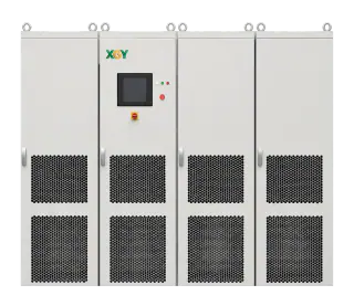
The XGY MVGS provides the programmable medium-voltage interface on the input side of a full-power SST validation bench. The current selection guide lists configurable direct output from 5 kV to 35 kV, standard capacity from 1 MVA to 10 MVA with project expansion to 20 MVA and above, and four-quadrant operation that can return absorbed energy to the facility grid. The MVGS does not replace the opposite-port source or load, protection, safety and measurement layers; final capabilities and interfaces are engineered per programme and reviewed against the DUT, test plan and facility.
FAQ
Frequently asked questions
Can one machine test an SST completely?
No. Full-power SST validation is a three-block system: a programmable MV grid interface on the input, a regenerative DC load or battery emulator on the output, and a measurement and safety layer around both. A medium-voltage grid simulator owns the input block — the grid events, ride-through profiles and P/Q interaction — while the output block needs its own controllable DC equipment.
How much facility power does a full-power SST bench need?
Far less than the ratings suggest, if the bench is regenerative. With a four-quadrant grid simulator and a regenerative DC side, most of the test power circulates through the chain and returns to the facility mains; the supply covers system losses plus margin. Exact figures depend on configuration and are established during facility review — see the lab-planning guide for the site checklist.
Do I still need scaled or HIL testing if I have a full-power bench?
Yes — they answer different questions. Scaled prototypes and hardware-in-the-loop remain the right tools for control-algorithm development and software regression, at a fraction of the cost and risk. The full-power bench exists for what they cannot reach: real insulation and partial-discharge behaviour, megawatt thermal performance, true fault energy and full multi-module interaction.
Does passing bench tests mean the SST is certified?
No. The bench executes standard-oriented test procedures and produces the evidence; certification is granted by the relevant bodies against the applicable standards for your project and jurisdiction. Supporting a test is not holding a certificate — confirm the compliance pathway with your certifier early.
What is the long-lead item in building this bench?
Usually the facility, not the equipment: medium-voltage supply capacity, protection and earthing engineering, cooling and physical logistics for multi-tonne cabinets all carry long lead times. Start the site survey in parallel with the equipment RFQ — the facility-planning guide walks the checklist.
Keep exploring
Related technical resources
Related articles
Grid Simulator Fundamentals
What Is a Grid Simulator? A Plain-English Guide
A grid simulator is a programmable AC source that reproduces grid behaviour — sags, swells, harmonics, ride-through events — for lab testing. What it does, who needs one, and how to spec it.
Read article
Technical Article
What Is a Solid-State Transformer (SST)? Architecture, Limits, and MVGS Testing
An engineering guide to solid-state transformer architecture, limits, and the role of a medium-voltage grid simulator in full-power SST validation.
Read article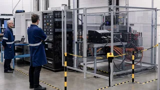
Technical Article
Regenerative AC/DC Source Planning for EV and Power Electronics Test
A planning guide for regenerative AC/DC sources used in EV chargers, inverters, grid simulation, and power electronics validation.
Read article