
Lightwave Component Analyzers
XLA-6433D / XLA-6433F / XLA-6433H / XLA-6433L Lightwave Component Analyzer
Electrical and Optical Frequency-Response Characterization
XLA-6433D/F/H/L combines E/E, E/O, O/E and O/O measurements for electrical and optical component characterization. Guided calibration, frequency sweeps and multi-window analysis support amplitude, phase, bandwidth and group-delay measurements.
Get a Quote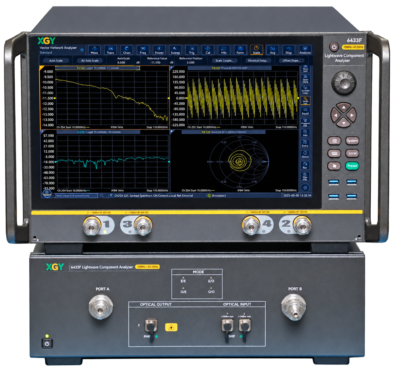
- Measurement modes
- E/E, E/O, O/E and O/O
- Frequency resolution
- 1 Hz
- Working wavelength
- 1310 ± 20 nm
- External optical sources
- 1260 nm to 1630 nm
Overview
XLA-6433D/F/H/L combines E/E, E/O, O/E and O/O measurements for electrical and optical component characterization. Guided calibration, frequency sweeps and multi-window analysis support amplitude, phase, bandwidth and group-delay measurements.
Product & Measurement Gallery
Integrated Measurement Interface
Multi-Functional Toolbox
Large Dynamic Range, Low Measurement-Path Noise
Electro-Optical Device Characterization
Optoelectronic Device Frequency Response
Phase-Frequency Response and Group Delay
User-Defined Data and Fixture De-Embedding
Single-Ended and Balanced Photoelectric Devices
Additional product details
The XLA-6433D/F/H/L integrated platform combines broadband hardware, a network error model and calibration algorithms for one-click frequency sweeps. Frequency interval and intermediate-frequency (IF) bandwidth can be set for each measurement.
Multi-window S11 and S21 analysis shows reflection and transmission characteristics of electro-optical modulators and directly modulated lasers. Photodetector testing includes rapid 3 dB bandwidth analysis; phase-frequency measurements support group-delay analysis.
Flat-response internal components and selectable IF bandwidth provide a large dynamic range and reduced trace noise. Internal and external optical sources support CWDM and DWDM component measurements.
Product image shows the XLA-6433F configuration.
Key Capabilities & Applications
Integrated measurement modes
Working wavelengths are 1310 ±20 nm and 1550 ±20 nm; external optical sources cover 1260–1630 nm. Select the model and optical path for the DUT.
Calibration and de-embedding
Guided electrical/optical calibration and user-defined or fixture de-embedding data support probe and fixture compensation.
Detector and balanced analysis
Photodetector measurements include 3 dB bandwidth analysis. Single-ended and balanced configurations support differential gain and common-mode rejection.
All capabilities and operating conditions
Guided calibration
Guided electrical and optical-path parameter calibration provides an operation process for measurement setup.
Fixture de-embedding
User-defined or fixture data compensates probe errors for on-chip measurements.
Balanced measurements
Single-ended and balanced configurations support differential gain and common-mode rejection measurements.
Common applications
- Electro-optical modulators and directly modulated lasers
- PIN and APD photodetectors
- Optical transmitting and receiving components
- Passive optical devices, including fiber filters
Technical Specifications
| Parameter | Specification |
|---|---|
| Measurement modes | E/E, E/O, O/E and O/O |
| Frequency resolution | 1 Hz |
| Frequency accuracy | ±1 × 10⁻⁷ |
| Working wavelength | 1310 ± 20 nm; 1550 ± 20 nm |
| Maximum Safe Average Input Power | |
| Input 1 | +7 dBm |
| Input 2 | +17 dBm |
| Average input optical power measurement accuracy | ±0.5 dB |
| External optical sources | 1260 nm to 1630 nm |
View all 10 specifications
| Parameter | Specification |
|---|---|
| Photodetector bandwidth analysis | 3 dB bandwidthStated for the series |
| Extinction ratio | > 20 dBStated for the series |
Detailed performance and interface tables (3)
| Parameter | XLA-6433D | XLA-6433F | XLA-6433H | XLA-6433L |
|---|---|---|---|---|
| Modulation Frequency Range (technical specifications) | 10 MHz to 26.5 GHz | 10 MHz to 43.5 GHz | 10 MHz to 50 GHz | 10 MHz to 67 GHz |
| Frequency Accuracy | ±1 × 10⁻⁷ | ±1 × 10⁻⁷ | ±1 × 10⁻⁷ | ±1 × 10⁻⁷ |
| Frequency Resolution | 1 Hz | 1 Hz | 1 Hz | 1 Hz |
| Working Wavelength | 1310 ± 20 nm; 1550 ± 20 nm | 1310 ± 20 nm; 1550 ± 20 nm | 1310 ± 20 nm; 1550 ± 20 nm | 1310 ± 20 nm; 1550 ± 20 nm |
| Average Output Optical Power Range | -2 dBm to +4 dBm | -2 dBm to +4 dBm (1310 nm); -2 dBm to +5 dBm (1550 nm) | -2 dBm to +4 dBm (1310 nm); -2 dBm to +5 dBm (1550 nm) | -2 dBm to +4 dBm (1310 nm); -2 dBm to +5 dBm (1550 nm) |
| Maximum Safe Average Input Power — Input 1 | +7 dBm | +7 dBm | +7 dBm | +7 dBm |
| Maximum Safe Average Input Power — Input 2 | +17 dBm | +17 dBm | +17 dBm | +17 dBm |
| Average Output Optical Power Accuracy | ±0.5 dB | ±0.5 dB | ±0.5 dB | ±0.5 dB |
| Average Input Optical Power Measurement Range — Input 1 | -35 dBm to +5 dBm | -35 dBm to +5 dBm | -35 dBm to +5 dBm | -35 dBm to +5 dBm |
| Average Input Optical Power Measurement Range — Input 2 | -25 dBm to +15 dBm | -25 dBm to +15 dBm | -25 dBm to +15 dBm | -25 dBm to +15 dBm |
| Average Input Optical Power Measurement Accuracy | ±0.5 dB | ±0.5 dB | ±0.5 dB | ±0.5 dB |
Models: XLA-6433D, XLA-6433F, XLA-6433H, XLA-6433L
| Parameter | XLA-6433D | XLA-6433F | XLA-6433H | XLA-6433L |
|---|---|---|---|---|
| Minimum Measurable Frequency Response | - | - | -60 dB | -55 dB |
| Relative Frequency Response Accuracy | ±0.7 dB | ±1.6 dB | ±1.6 dB | ±2.2 dB |
| Absolute Frequency Response Accuracy | ±1.8 dB | ±2.0 dB | ±2.5 dB | ±2.7 dB |
| Frequency Response Repeatability | ±0.3 dB | ±1.0 dB | ±1.7 dB | ±1.7 dB |
| Group Delay Measurement Accuracy | ±13 ps | ±18 ps | ±18 ps | ±31 ps |
| Phase Measurement Accuracy | ±3.5° | ±4.2° | ±4.2° | ±6.0° |
| Maximum Weight | 56 kg | 60 kg | 60 kg | 63 kg |
| Dimensions (W × H × D; excluding feet, hands) | 421 × 400 × 600 mm | 421 × 400 × 600 mm | 421 × 400 × 600 mm | 421 × 400 × 600 mm |
| Maximum Power Consumption | 600 W | 600 W | 600 W | 600 W |
Models: XLA-6433D, XLA-6433F, XLA-6433H, XLA-6433L
| Statement | XLA-6433D | XLA-6433F | XLA-6433H | XLA-6433L |
|---|---|---|---|---|
| Product overview | 10 MHz to 20 GHz | 10 MHz to 43.5 GHz | 10 MHz to 50 GHz | 10 MHz to 67 GHz |
| Technical specifications | 10 MHz to 26.5 GHz | 10 MHz to 43.5 GHz | 10 MHz to 50 GHz | 10 MHz to 67 GHz |
| Ordering description — primary instruments | 10 MHz to 26.5 GHz | 10 MHz to 26.5 GHz | 10 MHz to 26.5 GHz | 10 MHz to 26.5 GHz |
Conflicting modulation-frequency ranges are listed. Confirm the range of the selected configuration before ordering.
Performance notes
The XLA-6433D/F/H/L built-in optical power meter monitors input optical power in real time. Advanced settings enable polarization-maintaining laser-source output in CW mode, with an extinction ratio greater than 20 dB.
The CW output supplies a polarization-maintaining laser source for an M-Z type LiNiO3 modulator. The toolbox example shows an optical-power measurement range of -35 dBm to +5 dBm.
The safe average input-power limits are distinct from the optical-power measurement ranges.
A dash indicates that no minimum measurable frequency-response value is specified. It does not indicate zero.
Dimensions exclude “feet, hands”. No alternative dimensional definition is specified.
Specifications are subject to change without notice.
Models, Configuration & Compatibility
XLA-6433D · XLA-6433F · XLA-6433H · XLA-6433L
| Model | Product Overview | Technical Specifications | Order Information — Primary Instruments | Frequency-Range Qualification |
|---|---|---|---|---|
| XLA-6433D | 10 MHz to 20 GHz | 10 MHz to 26.5 GHz | 10 MHz to 26.5 GHz | 20 GHz in overview; 26.5 GHz in specifications. Confirm range before ordering. |
| XLA-6433F | 10 MHz to 43.5 GHz | 10 MHz to 43.5 GHz | 10 MHz to 26.5 GHz | 26.5 GHz in ordering; 43.5 GHz in specifications. Confirm range before ordering. |
| XLA-6433H | 10 MHz to 50 GHz | 10 MHz to 50 GHz | 10 MHz to 26.5 GHz | 26.5 GHz in ordering; 50 GHz in specifications. Confirm range before ordering. |
| XLA-6433L | 10 MHz to 67 GHz | 10 MHz to 67 GHz | 10 MHz to 26.5 GHz | 26.5 GHz in ordering; 67 GHz in specifications. Confirm range before ordering. |
Standard delivery contents
- Power Cord Assembly — Standard three-core power cord
- User Manual — /
- Product Certification — Certificate of Conformance
- Metrology Level Optical Fiber Patch Cord — /
- USB Cable — /
Model selection details
The XLA-6433D/F/H/L overview, technical specifications and ordering descriptions list different frequency limits. Confirm the selected model’s modulation-frequency range before ordering.
Control interfaces and software
The integrated measurement interface combines E/E, E/O, O/E and O/O modes with source-wavelength, optical-input-port and power controls. Electrical and optical-path calibration use guided prompts, and user-defined de-embedding data can be applied to optical and RF measurement paths.
Guided calibration · Fixture de-embedding
Technical Resources
Selection guidance
Format: Lightwave component analyzer
Coverage: Model-dependent modulation frequency range; confirm ordering limits
Best for: Bandwidth, amplitude-frequency response, phase-frequency response and group-delay characterisation.
View the Lightwave Component Analyzers categorySend the operating envelope, configuration and acceptance evidence you need; the quotation confirms model, options and delivery documentation.