
Products
Lightwave Component Analyzers
Lightwave Component Analyzers for Component Characterization
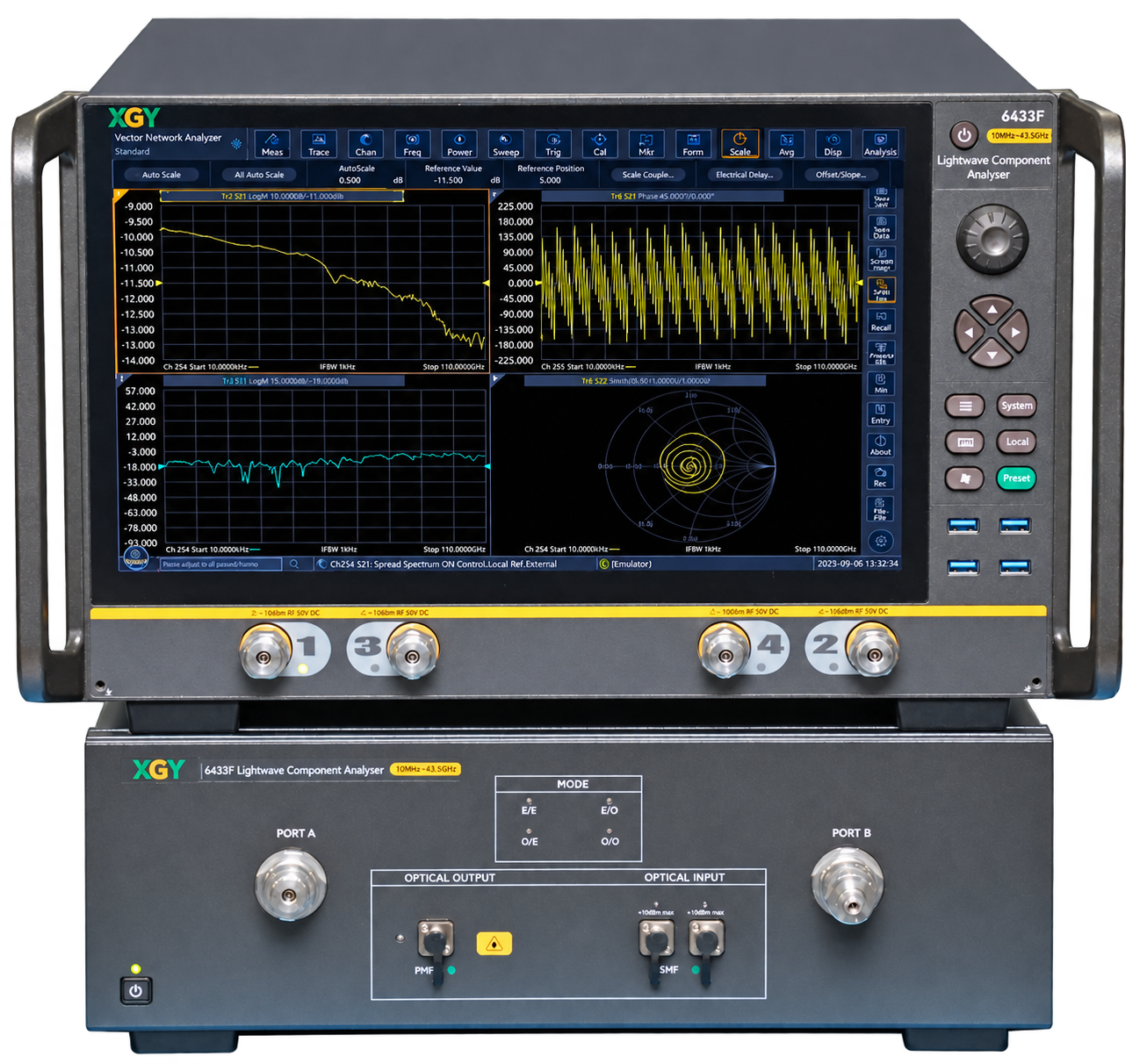
Lightwave component analyzers characterize electrical and optical components through amplitude-frequency response, phase-frequency response, bandwidth and group-delay measurements. The XLA-6433D/F/H/L platform combines E/E, E/O, O/E and O/O measurement modes with guided electrical and optical-path calibration, multi-window S11 and S21 analysis, and fixture de-embedding.
Applications include electro-optical modulators, directly modulated lasers, PIN and APD photodetectors, optical transmitters and receivers, and passive optical components. Start with the device conversion path, working wavelength, optical input power and calibration workflow.
Confirm the selected model's modulation-frequency range and ordering configuration when requesting a quotation, as the technical specifications and ordering information state different upper frequency limits.
Lightwave Component Analyzers product list
Selection path
Lightwave Component Analyzer Selection
Match the measurement path and device type, then review model-specific optical, response and general specifications. Confirm the required modulation-frequency range and configuration before ordering.
- XLA-6433D / XLA-6433F / XLA-6433H / XLA-6433LLightwave component analyzer
- Coverage
- Model-dependent modulation frequency range; confirm ordering limits
- Best fit
- Bandwidth, amplitude-frequency response, phase-frequency response and group-delay characterisation.