
RF Accessories
XDA-1000 / XDA-2000 Active Directional Antennas
Active Directional Antennas for YSA-P400
Directional reception, a switchable amplifier and live pointing information for YSA-P400 measurements from 500 MHz to 10 GHz or 20 GHz, depending on model.
Get a Quote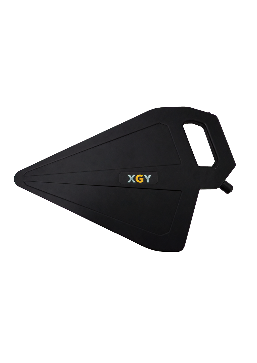
- XDA-1000
- 500 MHz to 10 GHz
- XDA-2000
- 500 MHz to 20 GHz
- Amplifier Gain
- 20 dB / 16 dB typical
- Weight
- 680 g
Overview
XDA-1000 and XDA-2000 combine directional reception with amplifier and bypass modes for signal search, interference localization and field-strength surveys. XDA-1000 covers 500 MHz to 10 GHz; XDA-2000 extends coverage to 20 GHz.
The YSA-P400 workflow displays antenna mode, pitch, roll and heading, and loads model-specific antenna-factor data. Position, signal level and antenna attitude can be correlated during mapping.
Product & Measurement Gallery
Connection Status and Working Mode
Confirm antenna connection and bypass or amplifier mode from the measurement interface.
Automatic Antenna-Factor Loading
Load the model-specific amplifier-on or amplifier-off correction profile for field-strength conversion.
Real-Time Antenna Attitude
View pitch, roll, and heading together with spectrum amplitude and field-strength information.
GNSS Mapping
Correlate position, received signal strength, and antenna attitude for signal search and coverage analysis.
XDA-1000 Gain
Amplifier-off/on gain response from 500 MHz to 10 GHz. The plots show amplifier-off/on gain, antenna factor, VSWR, and typical radiation patterns for each model. Use each plot only within its stated model and frequency conditions.
XDA-1000 Antenna Factor
Amplifier-off/on antenna-factor response from 500 MHz to 10 GHz. The plots show amplifier-off/on gain, antenna factor, VSWR, and typical radiation patterns for each model. Use each plot only within its stated model and frequency conditions.
XDA-1000 VSWR
Amplifier-off/on VSWR response from 500 MHz to 10 GHz. The plots show amplifier-off/on gain, antenna factor, VSWR, and typical radiation patterns for each model. Use each plot only within its stated model and frequency conditions.
XDA-1000 Radiation Patterns
Typical radiation patterns at 4, 6, and 8 GHz. The plots show amplifier-off/on gain, antenna factor, VSWR, and typical radiation patterns for each model. Use each plot only within its stated model and frequency conditions.
XDA-2000 Gain
Amplifier-off/on gain response from 500 MHz to 20 GHz. The plots show amplifier-off/on gain, antenna factor, VSWR, and typical radiation patterns for each model. Use each plot only within its stated model and frequency conditions.
XDA-2000 Antenna Factor
Amplifier-off/on antenna-factor response from 500 MHz to 20 GHz. The plots show amplifier-off/on gain, antenna factor, VSWR, and typical radiation patterns for each model. Use each plot only within its stated model and frequency conditions.
XDA-2000 VSWR
Amplifier-off/on VSWR response from 500 MHz to 20 GHz. The plots show amplifier-off/on gain, antenna factor, VSWR, and typical radiation patterns for each model. Use each plot only within its stated model and frequency conditions.
XDA-2000 Radiation Patterns
Typical radiation patterns at 6, 12, and 18 GHz. The plots show amplifier-off/on gain, antenna factor, VSWR, and typical radiation patterns for each model. Use each plot only within its stated model and frequency conditions.
Additional product details
Active Directional Antennas for YSA-P400
The XDA-1000 and XDA-2000 combine directional reception, a switchable broadband amplifier, and real-time antenna attitude sensing for YSA-P400 spectrum analyzer field workflows. They support spectrum monitoring, signal search, interference localization, field-strength surveys, and coverage mapping from 500 MHz to 10 GHz or 20 GHz.
Use amplifier mode when additional active gain is appropriate for a lower-level signal. Manual bypass supports stronger-signal measurements and extends the practical measurement range of the antenna and connected analyzer combination.
Model Selection
Choose XDA-1000 for measurements through 10 GHz and its higher 20 dB typical amplifier gain. Choose XDA-2000 when the workflow requires coverage above 10 GHz. Above 12 GHz the XDA-2000 trades passive gain for reach, so budget link margin from the 12 GHz breakpoint rather than from its lower-band figure, and expect the narrower 15 GHz beamwidth to give a sharper bearing at the cost of a slower search.
Directional and Active Operation
Directional response helps the operator compare signal level as the antenna bearing changes. The integrated amplifier improves active sensitivity where appropriate, while bypass mode supports stronger signals. Gain, beamwidth, front-to-back ratio, VSWR, amplifier gain, and amplifier noise figure values remain model- and frequency-dependent where stated.
YSA-P400 Antenna Workflow
The YSA-P400 interface can display antenna connection status and bypass or amplifier mode. Model-specific amplifier-on and amplifier-off antenna-factor data supports correction-profile loading for field-strength conversion.
Pitch, roll, and heading can be shown together with spectrum amplitude and field-strength information. In mapping workflows, GNSS measurement position, received signal strength, and antenna attitude can be correlated for signal search, coverage analysis, and on-site interference investigation.
Shared Mechanical and Interface Specifications
| Parameter | Both models |
|---|---|
| Polarization | Linear |
| Typical VSWR | <2.0 |
| RF connection | N female, 50 ohm |
| Measured attitude | Pitch, roll, and heading |
| Azimuth range | 0 to 360 deg |
| Pitch range | -180 to +180 deg |
| Roll range | -90 to +90 deg |
| Power and host connection | USB Type-C; USB Type-C to USB Type-A host cable |
| Dimensions | 430 x 270 x 35 mm |
| Weight | 680 g |
Engineering Overview
Connected to a YSA-P400 spectrum analyzer, the active directional antenna combines directional response with a switchable broadband amplifier to improve sensitivity when locating low-level RF sources. Bypass mode supports stronger signals and wider practical measurement range.
An integrated attitude and heading reference system reports azimuth, pitch, and roll in real time. The YSA-P400 measurement workflow can correlate pointing direction with spectrum amplitude, field strength, and position data for more efficient search and survey work.
- Broad Frequency Coverage: Continuous operation from 500 MHz to 10 GHz or 20 GHz, depending on the selected model.
- Directional Response: Typical passive gain up to 5 dBi supports source localization and directional field measurements.
- Switchable Amplifier: A built-in broadband amplifier provides 20 dB or 16 dB typical gain with manual bypass.
- Attitude Measurement: Integrated heading, pitch, and roll sensing provides real-time pointing information.
- YSA-P400 Integration: 50 MHz calibration spacing supports automatic antenna-factor loading in the YSA-P400 measurement workflow.
- Field-Ready Form: A 680 g enclosure, integrated handle, and USB-powered operation support extended handheld use.
Feature Detail
- Directional Signal Search: Use directional response together with live spectrum level and antenna attitude to narrow the bearing of an unknown or interfering emitter.
- Amplifier and Bypass Modes: Use the built-in broadband amplifier for lower-level signals and switch to bypass mode as appropriate for stronger signals and the connected host instrument.
- Automatic Antenna-Factor Workflow: Frequency-indexed amplifier-on and amplifier-off antenna-factor data supports field-strength conversion in the YSA-P400 workflow.
- Real-Time Attitude Display: Pitch, roll, and heading can be displayed with spectrum amplitude and field-strength information.
- GNSS Mapping: Correlate measurement position, received signal strength, and antenna attitude for signal search and coverage assessment.
- Portable Measurement: A 680 g enclosure, integrated handle, and USB-powered operation support handheld laboratory and field measurements.
Key Capabilities & Applications
Choose the coverage
XDA-1000 has 20 dB typical amplifier gain. XDA-2000 has 16 dB typical amplifier gain, with typical passive gain of 5 dBi from 500 MHz to 12 GHz and 2.4 dBi from 12 to 20 GHz.
Switch amplifier or bypass
Use the broadband amplifier for lower-level signals or manual bypass for stronger signals. Gain, noise figure and directional response remain model- and frequency-dependent.
Measure pointing and field strength
Live pitch, roll and heading accompany spectrum measurements. Amplifier-on and amplifier-off antenna factors use 50 MHz calibration spacing for the YSA-P400 correction workflow.
All capabilities and operating conditions
Coverage Options
XDA-1000 covers 500 MHz to 10 GHz; XDA-2000 extends coverage to 20 GHz.
Switchable Amplifier
Manual bypass plus 20 dB typical gain on XDA-1000 or 16 dB typical gain on XDA-2000.
Directional Measurement
Passive gain, beamwidth, and front-to-back performance support signal-source localization.
Attitude Sensing
Integrated azimuth, pitch, and roll measurement reports antenna pointing information in real time.
YSA-P400 Integration
Connection status, working mode, antenna-factor loading, attitude display, and mapping support the field workflow.
Handheld Form
A 680 g enclosure, integrated handle, and USB Type-C connection support portable measurements.
Common applications
- Signal Search and Interference Hunting
- Field-Strength Surveys
- Coverage and Mapping
- RF Test and Monitoring
- Signal search and interference hunting — use antenna direction, live signal level, and attitude information to narrow a possible emitter bearing.
- Field-strength surveys — load the corresponding antenna-factor data for the selected model and working mode.
- Coverage mapping — combine GNSS measurement points, received signal strength, and antenna attitude.
- Portable RF measurement — support spectrum monitoring, signal searching, interference detection, field-strength testing, and coverage analysis with YSA-P400.
Applications and test requirements
Signal Search and Interference Hunting
Use directional response, live spectrum level, and antenna attitude to narrow the bearing of unknown or interfering emitters.
Field-Strength Surveys
Apply stored antenna factors to convert measured levels into field-strength results across the calibrated frequency range.
Coverage and Mapping
Combine GNSS measurement points, received signal strength, and antenna attitude for multidimensional coverage assessment.
RF Test and Monitoring
Support spectrum monitoring, signal searching, interference detection, field-strength testing, and coverage analysis.
Technical Specifications
| Parameter | Specification |
|---|---|
| Frequency Range | XDA-1000: 500 MHz to 10 GHz; XDA-2000: 500 MHz to 20 GHz |
| Typical Amplifier Gain | XDA-1000: 20 dB; XDA-2000: 16 dB |
| Typical Passive Gain | XDA-1000: 5 dBi; XDA-2000: 5 dBi from 0.5 to 12 GHz and 2.4 dBi from 12 to 20 GHz |
| Half-Power Beamwidth | XDA-1000: 66 deg at 6 GHz; XDA-2000: 68 deg at 6 GHz and 35 deg at 15 GHz |
| Front-to-Back Ratio | XDA-1000: >15 dB; XDA-2000: >14 dB |
| RF Connection | N female, 50 ohm |
| Measured Attitude | Pitch, roll, and heading |
| Weight | 680 g |
View all 16 specifications
| Parameter | Specification |
|---|---|
| Typical Amplifier Noise Figure | XDA-1000: 1.5 dB; XDA-2000: 1.9 dB |
| Calibration Points | XDA-1000: 191; XDA-2000: 39150 MHz spacing |
| Maximum Field Strength | XDA-1000: 17 V/m at 6 GHz; XDA-2000: 16 V/m at 6 GHz and 52 V/m at 15 GHzAmplifier mode |
| Polarization | Linear |
| Typical VSWR | <2.0 |
| Angle Ranges | Azimuth: 0 to 360 deg; pitch: -180 to +180 deg; roll: -90 to +90 deg |
| Power and Host Connection | USB Type-C; USB Type-C to USB Type-A host cable |
| Dimensions | 430 x 270 x 35 mm |
Specifications are subject to change without notice.
Models, Configuration & Compatibility
XDA-1000 · XDA-2000
Control interfaces and software
With a YSA-P400 spectrum analyzer, the antenna workflow can show connection and working mode, load the corresponding antenna-factor data, display pitch, roll, and heading, and correlate GNSS measurement points with received signal strength and antenna attitude.
Bypass / Amplifier Status · Automatic Antenna-Factor Loading · Azimuth / Pitch / Roll · GNSS Mapping
Order codes and configuration are confirmed in the quotation.
Technical Resources
Selection guidance
Format: Active directional antenna
Coverage: 500 MHz to 10 GHz or 20 GHz; 20 dB / 16 dB typical amplifier gain
Best for: YSA-P400 signal search, interference hunting, and field-strength workflows.
Compare products in the RF Accessories categorySend the operating envelope, configuration and acceptance evidence you need; the quotation confirms model, options and delivery documentation.
Configure a YSA-P400 directional measurement kit
Share the target band, signal conditions, field-strength workflow, mapping needs, and selected XDA model so the complete YSA-P400 measurement path can be reviewed.
Related Products & FAQ
Spectrum Analyzers
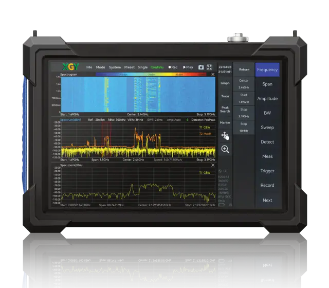
YSA-P400
Spectrum Analyzer
Frequency: 9 kHz to 40 GHz
View detailsRF Accessories
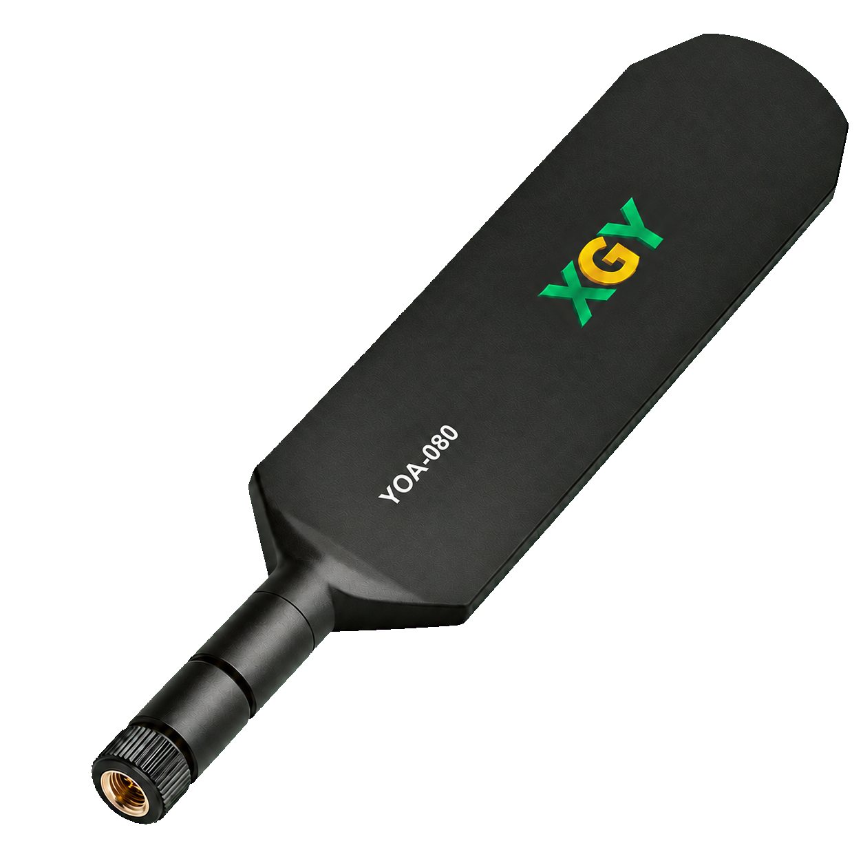
YOA-080
Portable Broadband Omnidirectional Antenna
Frequency range: 400 MHz to 8 GHz
View detailsSignal Generators
YSG-P400 Series
Portable RF Signal Generator
Frequency range: 200 MHz to 40 GHz
View details