

RF Power Amplifiers
GPA-10M100M-1000 RF Power Amplifier
Frequency range: 10-100 MHz; Output Psat: 1000 W minimum (60 dBm)
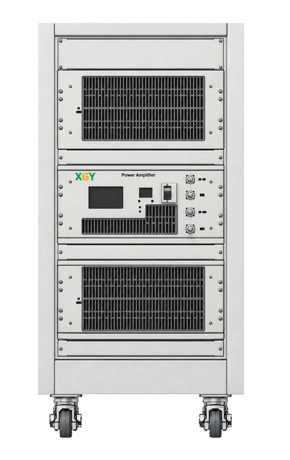
XGY GPA-10M100M-1000 is a solid-state RF power amplifier with a frequency range of 10 MHz to 100 MHz. It provides a minimum saturated output power of 1000 W (60 dBm) and a minimum small-signal gain of 60 dB.
- Frequency Range
- 10 to 100 MHz
- Output Power
- 1000 W (60 dBm) Psat, minimum
- Gain
- ≥ 60 dB Small-signal gain
- RF Interface
- N female / 7/16 female Input / output
GPA-10M100M-1000 overview
The GPA-10M100M-1000 is a solid-state RF power amplifier with a frequency range of 10 MHz to 100 MHz and output Psat of 1000 W minimum (60 dBm), for test setups that need kilowatt-level RF drive from a low-level signal generator. The power supply, cooling, protection and control sit inside one rack cabinet between the signal source and the load.
Small signal gain is 60 dB minimum, and output P1dB is 600 W minimum for work that must stay below compression. The RF input is an N female connector and the RF output is a 7/16 female connector.
The GPA-10M100M-1000 amplifier incorporates a built-in 380 V AC power supply and forced-air cooling, with thermal, input-overdrive and output-VSWR protection. Its input and output are matched to a typical impedance of 50 ohms. The amplifier size is 19 Inch 20U with 1.4 m Cabinet, and its control functions are power setting and on/off.
Key figures
- Size
- 19 Inch 20U with 1.4 m Cabinet
GPA-10M100M-1000 capabilities and applications
GPA-10M100M-1000 applications
-
EMC immunity testing
-
RF plasma generation
-
NMR and MRI RF excitation
-
High-power component stress testing
GPA-10M100M-1000 specifications
Full specification table — 8 published parameters
| Parameter | Specification |
|---|---|
| Electrical Characteristics | |
| Frequency range | 10-100 MHz |
| Small Signal Gain | 60 dB minimum Minimum |
| Output P1dB | 600 W Minimum |
| Output Psat | 1000 W minimum (60 dBm) Minimum |
| AC Voltage | 340-530 V AC |
| Impedance | 50 Ω Typical |
| Mechanical Specifications | |
| Size | 19 Inch 20U with 1.4 m Cabinet |
| Outline Drawing | |
| Tolerance | ±0.1 mm |
Detailed specification tables (7)
Electrical Characteristics (13 rows)
| Parameter | Symbol | Min | Typ | Max | Units |
|---|---|---|---|---|---|
| Frequency range | BW | 10 | — | 100 | MHz |
| Small Signal Gain | SSG | 60 | — | — | dB |
| Gain flatness | Δ GL | — | ±3 | — | dB |
| Noise Figure | NF | — | 6 | — | dB |
| Output P1dB | P1dB | 600 | — | — | W |
| Output Psat | Psat | 1000 | — | — | W |
| Spurious | Spur | — | -50 | — | dBc |
| Harmonics | HAM | — | -15 | — | dBc |
| Input VSWR | VSWRin | — | 2 | — | :1 |
| Output VSWR Alarm | / | — | 5 | — | :1 |
| AC Voltage | Vac | 340 | — | 530 | V AC |
| Power Consumption | Pdiss | — | — | 4500 | W |
| Impedance | I/O-IMP | — | 50 | — | Ohms |
1000 W corresponds to 60 dBm.
| Parameter | Value |
|---|---|
| Control functions | Power setting on/off |
| Protection functions | Input overdrive: ≤10 dBm; Over TEM: ≤+85 °C; VSWR protection: ≤5:1 |
| Cooling system | Built-in cooling system, forced-air cooling |
| Parameter | Value |
|---|---|
| Input / Output Connector | N Female / 7/16 Female |
| Forward / Reverse Coupling | N Female / N Female |
| Size | 19 Inch 20U with 1.4 m Cabinet |
| Parameter | Value |
|---|---|
| RF Input Power | +5 dBm |
| ESD sensitivity (HBm) | Class 0, passed 150 V |
Environmental Conditions (6 rows)
| Parameter | Min | Typ | Max | Units |
|---|---|---|---|---|
| Operating Temperature | 0 | — | +40 | °C |
| Non-operating Temperature | -20 | — | +60 | °C |
| Relative humidity | — | 95 | — | % |
| Altitude | 10,000 | feet | ||
| Shock / Vibration (MIL-STD-810F) | 25g rms (15 degree 2KHz) endurance, 1 hour per axis | — | ||
| Shock (non operating) | 20G for 11msc half sin wave, 3 axis both directions | — | ||
For a wider temperature range, please consult the manufacturer.
Optional items (5 rows)
| Number | Items | Payment |
|---|---|---|
| 1 | The input/output interfaces are located on the front panel. | STD(Optional) |
| 2 | The input and output interfaces are on the rear panel. | STD(Optional) |
| 3 | Safety lock (DB9) | STD(Optional) |
| 4 | Provides forward and reverse coupling ports | STD(Optional) |
| 5 | Gain and output power adjustment | PD |
The default input and output interface is in the back panel.
| Model | Description |
|---|---|
| GPA-10M100M-1000 | Solid State RF Power Amplifier, 10 MHz-100 MHz, Gain: 60 dB min., Psat: 1000 W min. (60 dBm), 380 V AC, built-in fan cooling |
Product and technical media
Outline Drawing
Unit: mm; Tolerance: ±0.1 mm
GPA-10M100M-1000 models, configuration and compatibility
GPA-10M100M-1000 selection guidance
- Format
- Solid-state amplifier in a 19-inch 20U cabinet
- Coverage
- 10-100 MHz; 1000 W (60 dBm) minimum saturated output; 60 dB minimum small-signal gain
- Best for
- Benches that need kilowatt-level drive from 10 to 100 MHz, with a built-in 380 V AC supply, forced-air cooling and VSWR protection.
GPA-10M100M-1000 technical resources
Request a quote for the GPA-10M100M-1000
Share the application, required configuration and documentation needs for the GPA-10M100M-1000, or compare it with other products in the RF Power Amplifiers category first. XGY Tek reviews each request and confirms model, options and delivery documentation in the quotation.
Before requesting a quote
For a GPA-10M100M-1000 request, state these points so the cabinet ships in the right configuration.
- Whether the test runs the amplifier in its linear region or in saturation, since the P1dB and Psat minimums differ.
- The AC supply available at the site, compared with the 340 V AC to 530 V AC input range.
- The rack position and cable routing at the installation, which decide the interface panel side.
- Whether the DUT or antenna can present a high VSWR, so the protection and alarm behaviour can be confirmed.
GPA-10M100M-1000 related products and FAQ
-
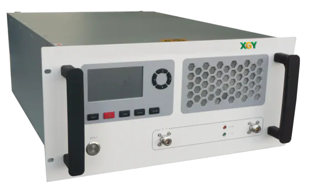
XPA-0727-200 RF Power Amplifier
Broadband RF power amplifier: 200 W CW output power, 0.7 to 2.7 GHz operating frequency
View details -
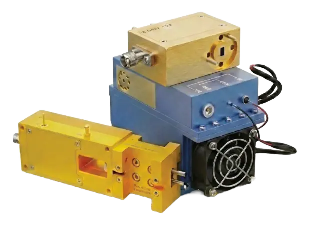
mmWave Active Waveguide Modules
Active Waveguide Modules Covering 33 to 500 GHz - Amplifiers, Multipliers, Mixers across mmWave/Sub-THz
View details
