In brief
Grid code compliance testing verifies that a defined hardware, firmware and settings configuration behaves as required at its electrical interface. In the United States, IEEE 1547 defines DER interconnection behaviour, IEEE 1547.1 defines conformance procedures, and UL 1741 is commonly used in the product evaluation pathway; Canadian and utility requirements must be mapped separately. Australia uses AS/NZS 4777.2 for relevant inverter products and a different NER/AEMO process for large generating systems. IEC 62116 supplies a repeatable anti-islanding method, not a universal market approval. A certification body, listing scheme or network operator — not the test source — decides whether the resulting evidence is accepted.
Key takeaways
- Separate requirement standards, test methods and conformity-assessment schemes: they answer what must happen, how it is demonstrated, and who may accept the evidence.
- A campaign is a matrix, not a pile of tests: every clause of every applicable standard mapped to a test condition, a method and an evidence artefact.
- The test families recur across all frameworks — ride-through, frequency and RoCoF, anti-islanding, power quality, protection settings — with parameters that differ by jurisdiction and edition.
- Capability and certification are different nouns: a laboratory bench executes standard-oriented procedures; certification is granted by bodies against the standard's full requirements, and the pathway involves them from the start.
- Australia has distinct paths: AS/NZS 4777.2 and applicable product-listing or network rules for relevant inverter equipment, and negotiated NER/AEMO performance standards, models and commissioning evidence for NEM generating systems.
Start with roles, not standard numbers
Grid code compliance is not one certificate and it is rarely one document. The project must identify four separate things: the technical requirement, the prescribed or accepted test method, the conformity-assessment route, and the authority that accepts the result at the connection point. The same test result can be useful in several markets without being automatically transferable between them.
| Instrument | Primary role | Typical scope | Who still has to accept it? |
|---|---|---|---|
| IEEE 1547 with its active amendment | US DER interconnection and interoperability requirements | Abnormal voltage and frequency response, power quality, controls, islanding, interoperability and verification | The adopting regulator, utility or authority having jurisdiction |
| IEEE 1547.1 | Conformance test procedures | Type, production, commissioning and periodic evaluations used to demonstrate IEEE 1547 functions | The applicable product certification and interconnection process |
| UL 1741 and applicable supplements | US product evaluation standard | Safety and interconnection equipment evaluation, including applicable grid-support functions | The certification organisation, authority having jurisdiction and utility under their respective scopes |
| IEC 62116 | International anti-islanding test method | Repeatable evaluation of islanding-prevention measures for utility-interconnected PV inverters | The market scheme or network rule that invokes the method |
| AS/NZS 4777.2 | Australia/New Zealand inverter requirements | Grid-interactive inverter behaviour, documentation, settings and relevant test requirements | The applicable listing scheme, regulator and network connection process |
| NER Schedule 5.2 and AEMO/NSP process | Australian NEM generating-system connection | Negotiated performance standards, plant models, studies, commissioning and ongoing compliance | The connecting Network Service Provider and AEMO in their defined roles |
| EU Requirements for Generators and national implementation | European legal framework implemented locally | Requirements by generating-module type, supplemented by national and system-operator rules | The relevant system operator and designated national authority |
This division prevents a common category error. IEEE publishes IEEE 1547 and 1547.1; UL 1741 is a standard used by certification organisations, not the organisation that approves every US interconnection. ISO/IEC 17025 accreditation concerns laboratory competence for a stated scope; it is not product certification. A network connection acceptance concerns a particular installation; it is not necessarily a transferable product listing. Keep those nouns separate in proposals, reports and purchase specifications.
Freeze the compliance basis before booking the laboratory
Begin with a one-page campaign basis, sometimes called a compliance passport. It should name the legal manufacturer, product family and rating variants; hardware revision and safety-critical bill of materials; firmware, parameter-set and communications versions; intended energy source; AC topology; target countries, states and networks; standard editions and amendments; assigned response category or regional profile; test boundary; certification body; and proposed laboratory. Record every open applicability question with an owner and due date.
That page is configuration control, not administration. A test performed on the wrong firmware, a default regional setting or an engineering sample with a different filter can be technically excellent yet irrelevant to the model submitted for approval. Obtain written agreement on the basis from the certification body or connection stakeholder before expensive witnessed testing. Where a product family is involved, agree which model is the worst case for each test family rather than assuming that the highest rating covers every stress.
Build a clause-to-test matrix
Turn the agreed basis into a controlled matrix. Do not organise it only by familiar test names. Begin at each applicable clause, include referenced documents and local source requirements, then link the requirement to the accepted method and evidence. One physical run may satisfy several rows, but every row must point to a measured result and every result must identify the tested configuration.
| Field | What to record | Why it matters |
|---|---|---|
| Requirement identity | Document, edition/amendment, clause, local rule and applicability decision | Prevents silent use of a superseded or unrelated requirement |
| Configuration | EUT model, rating, hardware, firmware, settings, operating point and environmental condition | Defines what the evidence actually represents |
| Stimulus and boundary | Precondition, event shape, duration, repetitions, source impedance and measurement location | Makes the run reproducible and exposes boundary assumptions |
| Response and decision rule | Required behaviour, calculation window, tolerances, uncertainty treatment and pass/fail owner | Stops acceptance criteria being invented after the run |
| Evidence link | Procedure step, run ID, raw file, plot, log, photograph, deviation and report section | Creates an auditable chain from clause to conclusion |
The recurring families normally include voltage and frequency operating ranges; trip and cessation behaviour; low-, high- and, where applicable, zero-voltage ride-through; post-event recovery; rate-of-change-of-frequency and active-power response; reactive-power capability and voltage-support modes; reconnection; intentional and unintentional islanding functions; power quality; command, monitoring and interoperability functions; and production or commissioning checks. Scope varies. A UPS, PV inverter, bidirectional battery converter and plant controller should not inherit the same matrix merely because all connect to AC power.
Define success beyond “did not trip.” Depending on the clause, the result may require remaining connected, ceasing to energise, supporting voltage, limiting active power, following a command, recovering within an allowed envelope, or reporting status correctly. Include any permitted exclusions and test tolerances before execution. Do not copy numerical limits from this guide: use the controlled standard copy and the approved local settings for the campaign.
Capability, accreditation, certification and connection acceptance
A grid simulator has an operating envelope and waveform capability. A laboratory may be accredited to ISO/IEC 17025 for particular methods, ranges and sites. A certification body may evaluate a defined product and authorise a mark or listing under its scheme. A utility or system operator may accept a product or generating system for a specific connection. These are four different decisions.
Ask to see scope, not just logos. Laboratory accreditation outside the required method, voltage range or location may not cover the work. A witnessed manufacturer test may be acceptable under one certification programme and rejected under another. A US Nationally Recognized Testing Laboratory has OSHA recognition only for standards and sites within its recognition scope; that status does not by itself grant a utility interconnection. Likewise, a product certificate does not prove that a plant model, protection scheme or commissioned installation meets site-specific obligations.
The practical rule is simple: engage the body that will make the final decision while the procedure is still editable. Agree the test location, witness points, sample selection, use of subcontractors, treatment of measurement uncertainty, reporting template, data-transfer method and retest rules. “Can generate the profile” is a useful equipment claim. “Certified to the grid code” is not a claim a source instrument can make.
Australia: product requirements and plant connection are different tracks
For relevant inverter products, confirm the current AS/NZS 4777.2 edition, amendment, product category and regional settings. At publication, the Clean Energy Council’s application guidance points to AS/NZS 4777.2:2020 Amendment 2:2024 and asks applicants to use suitably accredited testing and certification for the applicable product category. Approved-product listing, incentive eligibility and distribution-network acceptance are related but not identical decisions, so name the actual scheme in the campaign basis. Do not describe a listing as universal permission to connect.
For generating systems in the National Electricity Market, the NER connection process is plant-specific. The connection applicant submits proposed performance standards, data and model packages to the connecting Network Service Provider; AEMO reviews and negotiates matters within its role. The evidence set can include RMS and EMT models, design and settings data, studies, commissioning plans, test results and model validation. Equipment bench tests can characterise a converter and reduce model risk, but they do not reproduce every plant interaction or replace registered performance standards. AEMO’s official guidance also notes that some system behaviours are impractical or unsafe to demonstrate directly on site, making validated models and agreed partial demonstrations essential.
Australia also has separate market frameworks. Do not apply NEM terminology mechanically to the Wholesale Electricity Market in Western Australia; AEMO’s WEM generator-performance-standard and monitoring processes use their own rules and templates. The state, market, network and plant class must be explicit in the matrix.
United States, Canada and the wider IEC landscape
In the United States, IEEE 1547 defines the common technical baseline for DER interconnection, while IEEE 1547.1 provides the conformance procedures. Adoption still occurs through state rules, utility tariffs, interconnection agreements and other authority requirements. UL 1741 and its applicable supplement are commonly used in product evaluation, but the required edition, utility source requirement and certification marking must be confirmed for the destination. Treat “North American certified” as too vague for campaign control.
Canada has Canadian electrical certification requirements and provincial, territorial and utility interconnection rules. A US report or mark may be reusable only when the certification organisation’s Canadian scope and the applicable technical requirements support it. Record Canada as a separate market row rather than adding it after a US campaign is complete.
IEC publications provide internationally reusable technical language, but they are not global connection permission. IEC 62116 is specifically a test procedure for islanding-prevention measures used with utility-interconnected PV inverters. It does not cover every converter technology, every grid-support function or the complete product-safety case. A national rule may adopt it, modify how it is applied, or call up other IEC/EN standards. In Europe, Commission Regulation (EU) 2016/631 establishes the Requirements for Generators framework, while national implementation and system-operator requirements supply important parameters and procedures. Always map the IEC or EN method to the legal and scheme layer that invokes it.
Anti-islanding is not the opposite setting of ride-through
Ride-through asks the equipment to remain connected and behave predictably while the grid is still present but outside normal voltage or frequency conditions. Anti-islanding asks it to stop energising an unintended island after the upstream grid is absent. Both can produce abnormal local voltage and frequency, so a weak classification algorithm can pass one family by failing the intent of the other.
Test them as separate procedures with linked design review. Ride-through needs controlled grid events, defined pre-event power, response measurement during the event and recovery assessment. Anti-islanding typically needs the prescribed source, equipment under test, switching point and load arrangement, with real and reactive power balance controlled near the difficult detection condition. Record load component values and quality factors, steady-state balance before opening, switch timing, equipment output and the electrical quantity used to determine cessation. Intentional microgrid operation is a different operating mode and should not be confused with unintentional island prevention.
After firmware changes to phase-locked-loop, protection, ride-through, reconnection or grid-forming logic, rerun the impact assessment across both families. A faster trip is not automatically a safer compliance result if it violates an obligation to remain connected.
Engineer the test system, not only the waveform
Draw a single-line diagram for every materially different setup and mark the evidence boundary. A representative converter campaign may include the primary energy source or simulator, equipment under test, AC grid simulator, transformer or matching network, switchgear, anti-islanding load bank, cooling and auxiliaries, protection, emergency isolation, and measurement channels. At medium voltage or megawatt power, transformer vector group, grounding, neutral treatment, cable impedance, prospective fault level, source current limit and regenerative energy path can all change what reaches the equipment terminals.
Size the source in four dimensions: continuous voltage/current/power; short-duration current and overload; energy absorption or regeneration; and dynamic control bandwidth within the required load envelope. Confirm behaviour in every quadrant the equipment can enter. A simulator that reaches the commanded voltage only by saturating its current limit has not delivered the intended event. Capture the simulator’s commanded and measured waveform, internal limit flags and protection state so source clipping cannot masquerade as equipment response.
Define measurements from the decision rule backwards. Typical channels include phase voltages and currents at the agreed boundary, active and reactive power, frequency or phase, DC quantities, digital trip/contactor states, protection events, controller mode, setpoint receipt and status response. Use sensors with adequate insulation, bandwidth, range and phase performance; record transformer and transducer ratios. Synchronise power analysers, oscilloscopes, simulator logs and controller logs to a common trigger or documented time correlation. Preserve pre-trigger data. State sampling rates, filtering, RMS or sequence calculation, interpolation, time-window rules and measurement uncertainty before testing.
Calibration certificates should be current, traceable and applicable to the range used. A calibration sticker alone does not explain channel uncertainty. The report should include the measurement chain — sensor, cable, acquisition channel, scaling and analysis version — plus uncertainty where it can affect the conformity decision. Perform a setup verification run using known conditions before connecting the certification sample, and verify emergency stop, interlocks, discharge, grounding and safe-state behaviour under a reviewed laboratory procedure.
Design the evidence package before the first run
Each run needs a unique, immutable identifier. The run folder should contain the approved procedure revision; matrix rows addressed; sample serial number and configuration manifest; setup diagram and photographs; instrument and calibration register; preconditioning and ambient records where relevant; operator and witness record; commanded profile; unprocessed time-series data; event and communications logs; analysis script or software version; derived plots and calculations; pass/fail disposition; and all deviations or anomalies.
Keep raw data raw. Never overwrite it with resampled, renamed-channel or manually trimmed files. Store transformed data separately with the processing steps and units. Use access control, checksums or an equivalent integrity method, backed-up storage and a retention period agreed with the scheme owner. A plotted PDF is convenient for review but is not a substitute for source data when a reviewer questions a time window, channel scale or transient.
The final report should trace each conclusion back to a matrix row and run ID. It should describe limitations honestly: tests not performed, functions declared out of scope, substitutions, deviations, uncertainty effects and any reliance on analysis rather than direct observation. A “pass” without an identifiable decision rule is only an opinion.
A practical witnessed or accredited-laboratory workflow
- Pathway agreement: provide the product description, target markets and draft matrix to the certification body or accepting authority. Confirm sample selection, laboratory scope, witness level, subcontracting, deviations, retest and reporting rules.
- Readiness review: issue the controlled procedure, configuration manifest, schematics, risk assessment, instrumentation list and calibration status. Close open questions before the witness date.
- Engineering dry run: execute the procedure on a non-certification sample or under clearly labelled development status. Validate automation, trigger timing, source headroom, data channels and analysis without representing the data as witnessed evidence.
- Configuration lock: identify or seal the sample as the scheme requires; archive firmware hashes, settings exports and relevant bill-of-material revisions. Record any change after lock.
- Witnessed execution: follow the approved steps, retain contemporaneous observations and pause on unexpected behaviour. Do not quietly tune settings or repair data between repeats. Open a deviation and obtain disposition.
- Independent review: reconcile run inventory against the matrix, reproduce calculations from raw data, check uncertainty-sensitive margins, and have authorised reviewers approve the report.
- Closure: submit nonconformities and corrective actions through the agreed route. The certification or connection body decides the necessary retest and, separately, whether to issue a certificate, listing or acceptance.
Accreditation supports confidence in laboratory competence and process control; witnessing supports confidence that an agreed test was executed on the identified sample. Neither guarantees a positive product decision, and neither should be implied when it did not occur.
Sequence the campaign to expose inexpensive failures first
Run document and settings reviews before energisation. Then verify communications, operating modes, sensors and steady-state functions at reduced risk. Follow with nominal power-quality and control-function sweeps, protection boundary checks, anti-islanding development work, and finally the high-energy dynamic events and witnessed repetitions. The exact order depends on the approved method, but the economic principle is stable: find mapping, scaling and firmware errors before the laboratory and full-power assets are on the critical path.
Work backwards from the market date through certification or connection review, report issue, witnessed campaign, engineering campaign, sample build and design freeze. Reserve time for failure analysis, body review and partial retest. Availability of the EUT, source, load bank, transformer, instrumentation, witness and safety personnel must overlap; booking only the grid simulator does not create a laboratory slot.
Control changes after a passing test
Maintain a tested-configuration record linking model numbers to hardware, firmware, settings, safety components, filters, sensors and controller versions. For every component substitution, firmware release, rating extension or new operating mode, perform a documented compliance impact assessment. Map the changed functions to affected matrix rows and ask the certification body or network stakeholder to determine whether document review, similarity analysis, partial retest or a new campaign is required.
Do not assume a patch is “software only.” Protection timing, measurement filtering, communications fallback, reactive-current priority and thermal derating can change through code. At plant level, a control or settings change may also affect the validated model or agreed performance standard. Preserve approval correspondence with the same discipline as test data.
Common failure modes that good planning prevents
- Wrong compliance basis: the team uses an old amendment, wrong regional profile, unconfirmed IEEE category or US assumptions for Canada.
- Boundary confusion: voltage is verified at the simulator while cable or transformer drop means the equipment terminals saw a different event.
- Source saturation: current limiting, regeneration limits or control bandwidth distort the commanded profile without an obvious alarm in the final plot.
- Hidden mode conflicts: default volt-var, frequency-watt, export limit, ride-through or protection functions operate simultaneously and the observed response is attributed to the wrong controller.
- Timebase and filtering errors: unsynchronised instruments, undocumented RMS windows or transducer delay move a result across the decision boundary.
- Anti-islanding setup drift: load balance or component temperature changes between the precondition record and the opening event.
- Uncontrolled repetition: an operator changes a setting, reloads firmware or restarts a controller without creating a new configuration and run ID.
- Evidence gaps: screenshots replace raw data, calibration scope is missing, failed runs disappear, or plots cannot be regenerated.
- Over-broad conclusion: a component test is presented as plant compliance, or laboratory accreditation is presented as product certification.
Sample campaign checklist
Before testing, confirm that:
- the market, authority, network, product class, standard editions, amendments and local requirements are documented;
- the certification or connection stakeholder has reviewed the matrix and evidence plan;
- sample selection and family worst-case rationale are approved;
- hardware, firmware, settings and serial numbers are locked and recoverable;
- each clause maps to a procedure, configuration, operating point, decision rule and artefact;
- the source, transformer, load and protection envelope covers all planned quadrants and transients;
- single-line diagrams, safety review, interlocks and emergency procedures are approved;
- every measurement channel has defined range, bandwidth, scaling, time correlation and calibration status;
- dry runs have confirmed profiles, triggers, source headroom, automation and analysis;
- witness points, deviation authority, retest rules and report template are agreed;
- raw-data integrity, backup, access and retention are ready; and
- schedule and budget include technical review, corrective action and partial retest.
What this guide cannot decide
Only the current controlled standards, applicable law, certification scheme and responsible network parties can determine the required categories, settings, limits and evidence for a product or connection. This guide supplies a campaign method, not a compliance opinion. It also does not replace safety, EMC, endurance, insulation, cybersecurity or plant studies that may be required in parallel. Treat compliance evidence as a precise claim about an identified configuration and scope — no more, and no less.
Product fit
Where the MVGS fits
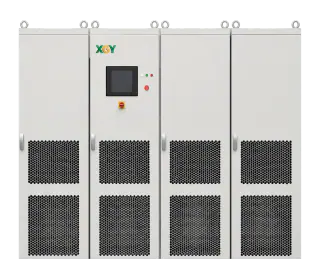
Within a compliance programme, the XGY MVGS medium-voltage grid simulator can generate scripted voltage, frequency, phase and waveform conditions for ride-through, response, power-quality and anti-islanding arrangements within the selected system configuration's validated operating envelope. It is one part of a complete test system that also needs suitable interfaces, protection, measurement, calibration and an evidence process. It can execute standard-oriented procedures and provide repeatable source records; it does not certify the equipment under test. At quote stage, the engineering review maps the target standards and test boundary to the required source envelope, profile library, instrumentation interfaces and evidence format.
FAQ
Frequently asked questions
What is the difference between IEEE 1547 and UL 1741?
They have different roles. IEEE 1547 specifies interconnection and interoperability requirements for distributed energy resources, and IEEE 1547.1 specifies conformance test procedures. UL 1741 is a product standard used by certification organisations to evaluate inverters, converters, controllers and interconnection equipment, including applicable grid-support functions. The required editions, supplements and utility source requirements are determined for the actual US jurisdiction; Canada has its own certification and interconnection requirements.
Can I certify my product on my own test bench?
You can generate evidence on it; certification is the body's grant under its scheme. Many schemes accept manufacturer-laboratory data under witnessing or recognition arrangements, others require accredited third-party laboratories for defined tests — the answer is scheme-specific and must come from your certifier at campaign design. Capable in-house benches reduce cost and iteration time either way; they never replace the pathway.
How do anti-islanding and ride-through requirements coexist?
Deliberately in tension, and both are tested: ride-through demands the device stay connected through grid disturbances; anti-islanding demands it disconnect promptly when the grid is genuinely gone. Compliance campaigns verify each behaviour under its procedure — IEC 62116's method for islanding, the code's profiles for ride-through — and, critically, that the device distinguishes the situations correctly rather than passing one test by failing the other's logic.
What is special about Australian compliance?
Two tracks must not be collapsed into one. Relevant inverter products are assessed to the applicable edition and amendment of AS/NZS 4777.2, including the required regional settings, and may also need an approved-product listing or network acceptance. In the NEM, larger generating systems follow the NER connection process with the Network Service Provider and AEMO: agreed performance standards, plant models, studies, commissioning and model-validation evidence. Equipment-level bench results can support that plant process but do not replace it.
Keep exploring