
In brief
There are five practical ways to test megawatt-scale power electronics: direct utility connection, back-to-back arrangements, a low-voltage source with a step-up transformer, power hardware-in-the-loop, and a full-power grid simulator. None is universally best. Each answers a different set of questions at a different cost, and mature programmes use several—the discipline is matching every test question to the least resource-intensive method that can legitimately answer it.
Key takeaways
- The method landscape is a portfolio, not a ranking—serious programmes combine methods across the development timeline.
- Direct utility connection excels at long, normal-condition running but usually cannot provide deliberate, repeatable abnormal events.
- Back-to-back testing circulates power between compatible converters—ideal for endurance and loss work, but not evidence of grid interaction.
- The step-up-transformer route reaches medium voltage economically, with the transformer's bandwidth, vector group, grounding and saturation behaviour present in every delivered event.
- PHIL brings simulated grid dynamics to real hardware within the power interface's stability, power and bandwidth envelope; a full-power grid simulator adds real terminal voltage, full operating power and programmable disturbances for the cases that require all three.
Select the method from the claim, not the available equipment. Define what must be proven, the operating point and disturbance, tolerable measurement uncertainty and required evidence. Then choose the least resource-intensive method that can reproduce those conditions at the device-under-test (DUT) boundary. The result is usually a portfolio: utility connection for field coexistence; back-to-back for endurance and loss; a characterised LV-source/transformer chain for suitable MV tests; power hardware-in-the-loop (PHIL) for simulated-system interaction; and a full-power grid simulator for controlled disturbances at actual terminals. No conclusion transfers automatically beyond its method’s boundary.
Method selection matrix
| Method | Best-fit question | Rated terminal voltage and power | Disturbance control and repeatability | Evidence it supports well | Inference it does not support by itself | Main facility dependency |
|---|---|---|---|---|---|---|
| A—Direct utility connection | Will the DUT operate reliably and coexist with the actual network over time? | Yes, at the approved point of connection and within the utility operating envelope | Low: abnormal events are normally neither deliberate nor repeatable | Commissioning, availability, normal-operation thermal soak, dispatch and communications in the field | Response to a specified sag, swell, frequency ramp, unbalance or fault that was not delivered | Utility agreement, compliant switchgear and protection, operating schedule and site access |
| B—Back-to-back | Can the power stage sustain real current, losses and thermal duty? | Often yes for converter loading; the electrical environment depends on the loop topology | High for power and thermal profiles; low for independent grid events unless extra source capability is added | Endurance, burn-in, efficiency mapping, cooling performance and repetitive operating cycles | Grid-code behaviour, network impedance interaction or protection response to an independent grid | A compatible partner converter, shared energy path, loss supply and coordinated protection |
| C—LV source plus step-up transformer | Can an existing LV source deliver this defined MV operating point or event faithfully? | Conditional on source, transformer, cables, protection and load ratings | Conditional: strong for steady state and slower events inside the measured transfer envelope | MV steady-state range, operating maps and characterised event families | Any event distorted by bandwidth, flux, vector-group, zero-sequence, grounding or recovery limits | Transformer selection, insulation coordination, source regeneration and chain characterisation |
| D—PHIL | How does real control or power hardware interact with a simulated network? | Real hardware up to the power-interface rating; scaling may be used if explicitly validated | High scenario repeatability inside the closed-loop stability and fidelity envelope | Weak-grid interaction, controls integration, protection logic, multi-device scenarios and model refinement | Stress or behaviour that depends on unrepresented full voltage, full current, thermal mass or insulation | Real-time model, interface algorithm, amplifier, sensors, deterministic timing and stability analysis |
| E—Full-power grid simulator | How does the DUT respond to a prescribed event at actual terminals and operating power? | Yes, within the simulator, facility and DUT envelopes | High when the delivered waveform and initial condition are qualified at the DUT terminals | Repeatable ride-through, frequency, unbalance, impedance, harmonic and protection tests at full scale | Conditions beyond simulator short-term current, voltage, bandwidth or energy envelope; accreditation is not automatic | Facility supply and regeneration, MV protection, cooling, safe test cell and high-bandwidth measurement |
Method A—direct utility connection
Setup and controls. Connect at a defined point through approved transformers, switchgear, earthing, metering and protection. Record the permitted voltage, frequency, real/reactive power, ramp-rate and switching envelope. Freeze DUT firmware and settings. The written switching sequence and named authority on each side govern energisation; a test script cannot override network instructions.
Instrumentation. Measure synchronised terminal voltage/current, DC quantities, breaker/interlock states, commanded and actual power, cooling and temperature. Combine long-duration trends with triggered capture for fast events. Record background distortion, unbalance and network configuration because “the utility” is not a fixed stimulus.
What it proves. Method A supports commissioning, stable export/import, dispatch, communications, normal-operation power quality, availability and thermal soak. It also reveals site-specific effects such as nearby loads, changing network strength and tap operation.
Limits and evidence gate. A clean month does not prove ride-through if no qualifying disturbance occurred. A coincidental fault counts only when its precondition, depth, phase, duration and recovery meet the procedure and valid instruments captured it. Accept evidence only for observed, documented network states. Deliberate abnormal testing requires explicit authorisation.
Method B—back-to-back power circulation
Setup and controls. Couple compatible converters through a common DC link, AC path or another engineered loop so the facility supplies mainly the losses. Define voltage and power/current regulators, startup, and safe trip behaviour. Check voltage, current, isolation, common-mode, grounding and fault-current compatibility—not only nameplate power.
Instrumentation. Measure every claimed efficiency boundary on a common timebase, plus DC-link voltage, phase current, relevant control states, cooling, temperature and facility input energy. Because loss may be the difference between two large powers, calculate uncertainty for that difference. Require energy-balance closure; unexplained energy signals a missed boundary, timing error or bad measurement.
What it proves. Method B suits full-current endurance, repeated cycles, thermal equilibrium, cooling, derating, burn-in and efficiency/loss mapping without dissipating all circulated power in a load bank.
Limits and evidence gate. The partner’s control and impedance are part of the environment, not an independent grid. Document loop modes, boundaries, energy balance, thermal stabilisation, protection and repeatability. Do not claim ride-through, frequency or weak-grid evidence unless a separate validated source actually produced those conditions.
Method C—low-voltage source plus step-up transformer
Setup and controls. Match transformer ratio, vector group, insulation, thermal duty, impedance and grounding to the DUT and event list. Add MV switching, protection, discharge, measurement and a sink/regenerative path where needed. Regulating the LV primary does not guarantee the requested loaded-secondary waveform.
Instrumentation. Measure both transformer sides simultaneously. Under representative load, characterise ratio/phase, relevant frequency response, leakage-related drop, magnetising current, inrush, temperature and event recovery. For asymmetric waveforms, retain voltage-time history because core state is an initial condition. Verify polarity, phase mapping, zero-sequence path and DUT-terminal waveform.
What it proves. A characterised chain can support MV steady state, voltage-range checks, efficiency maps and slower symmetrical variations when secondary measurements meet the agreed tolerance.
Limits and evidence gate. Bandwidth rounds transitions; leakage changes event depth; windings alter phase and zero sequence; asymmetry, low frequency or DC can cause saturation; recovery affects repetition. Qualify each waveform family at the loaded DUT terminals as faithful, usable with a quantified limitation, or not deliverable. An LV command is not MV stimulus evidence.
Method D—power hardware-in-the-loop
Setup and controls. PHIL closes a loop from real-time model through power interface and hardware response. Define timestep, solver, scaling, interface algorithm, sensor/amplifier transfer functions, filtering, compensation, delay and network/DUT impedance range. These are experimental conditions, not implementation details.
Instrumentation. Log model command, terminal output, feedback, interface error, limit flags, timestep overruns and clocks; independently record the physical terminals. Baseline a known load, then compare commanded, simulated and measured quantities over the claim’s relevant bandwidth. Preserve models, parameters, interface settings and software versions.
What it proves. PHIL supports weak-grid, changing-impedance, controller, multi-machine, protection and communications studies, plus rapid contingency exploration and model refinement.
Limits and evidence gate. Delay, filtering, bandwidth, sensors and HUT impedance affect stability and fidelity. A stable run can still be inaccurate, and interface oscillation can mimic DUT instability. Scaling needs an explicit similarity argument; it does not recreate insulation, absolute fault current or thermal mass. Accept results only inside a documented stability/fidelity envelope verified against known cases.
Method E—full-power grid simulator
Setup and controls. Put a four-quadrant programmable AC source between facility and DUT, with the DUT’s DC source, load or emulator completing the energy path. Coordinate MV switching/protection, grounding, auxiliaries, cooling, regeneration, communications and the test cell. Define initial condition, operating point, waveform, trigger, abort and recovery; check both source and sink envelopes for the complete sequence.
Instrumentation. Independently capture synchronised terminal voltages/currents, power, DC energy, protection contacts, commands, simulator limit flags and temperatures. Internal telemetry should not be the sole acceptance record. Qualify events with the intended load or justified surrogate, and store commands with measured waveforms.
What it proves. Inside its envelope, Method E combines actual terminal voltage, operating power and programmable disturbances for repeatable ride-through, frequency, unbalance, impedance, harmonic, mode-transition and protection tests under realistic loading.
Limits and evidence gate. “Full power” does not mean unlimited fault current, bandwidth, harmonic/negative-sequence output or absorbed energy. Facility regeneration adds another boundary, and equipment alone does not confer accreditation. Accept evidence only when the procedure permits the method, loaded terminal stimuli meet tolerance, initial conditions are controlled, limits are dispositioned, runs repeat and uncertainty supports the decision. The published 5 MVA, 13.8 kV MVGS sample is one configuration—not a universal event envelope.
A staged validation workflow
The stages are evidence gates, not a mandatory calendar. Move an individual claim forward only after the cheaper stage has removed the risks it can see.
- Define the evidence map. For every requirement, record the governing document and clause, DUT configuration, operating point, stimulus at the DUT boundary, measured response, pass/fail rule, uncertainty requirement and intended reviewer. If no pass/fail rule exists, agree one before booking a high-power facility.
- Verify models, controls and protection logic. Use offline simulation and controller-hardware-in-the-loop as precursors, then PHIL where real power-hardware interaction changes the answer. Challenge communications loss, sensor substitution, mode transitions and abort logic before applying full energy.
- Accumulate operating hours economically. Use Method B for endurance, thermal stabilisation and efficiency work where its loop topology represents the claimed stress. Resolve cooling, nuisance-trip and repeated-cycle issues here rather than during event-facility time.
- Use existing MV assets selectively. Allocate Method C only the steady-state points and event families that a measured source-transformer chain reproduces. Requalify after transformer, cable, grounding, control or measurement changes.
- Reduce the decisive scenario set. Use Method D to explore network strength, fault location, controller combinations and parameter sensitivity. Select worst-relevant and boundary cases from evidence, not from a desire to run every modelled scenario at full power.
- Qualify and execute full-power events. On Method E, commission from de-energised checks through low-energy proving to the intended operating point. Qualify stimuli, run forced-fail checks of protection where safe and authorised, then execute the controlled verification matrix with configuration lock and independent capture.
- Confirm field coexistence. After laboratory risks are closed, Method A demonstrates commissioning, dispatch and long-duration behaviour on the actual network. Feed field observations back into the model and regression set; do not use field soak to fill missing controlled-event evidence.
Engineering acceptance and evidence matrix
Do not invent generic pass thresholds for a product family. Take numerical limits from the applicable grid code, test standard, connection agreement, customer specification or approved internal requirement, then record where each value came from.
| Acceptance gate | What must be defined before the run | Minimum retained evidence | Reject or repeat when |
|---|---|---|---|
| Stimulus validity | Boundary, initial condition, waveform tolerance, loading and recovery state | Command file plus independent measured waveform at the DUT terminals | The delivered condition falls outside tolerance, clips, saturates or starts from the wrong state |
| DUT response | Measurand, time window, calculation and pass/fail rule | Raw synchronised data, processed result and calculation version | A channel ranges out, loses time alignment or the calculation cannot be reproduced |
| Repeatability | Number and order of runs required by the governing procedure or risk plan | Run identifiers, overlays and disposition of outliers | Nominally identical runs diverge without an explained physical cause |
| Measurement validity | Range, bandwidth, calibration status, uncertainty and influence quantities | Instrument IDs, calibration records, scaling, sample rates and uncertainty budget | Uncertainty consumes the decision margin or the sensor cannot capture the event content |
| Configuration control | Hardware revision, firmware, parameters, model, wiring, grounding and protection | Signed configuration manifest, diagrams and change log | The tested configuration cannot be tied to the released article or later changes are undispositioned |
| Safe execution | Hazard controls, authorisation, interlocks, aborts and stored-energy state | Pre-run checklist, interlock/abort test and event log | A required safety control is bypassed, untested or behaves differently from the approved sequence |
An evidence pack should also include the test purpose and exclusions, DUT photographs/nameplate, one-line diagram, sensor locations and polarity, facility configuration, environmental and cooling conditions, anomaly log, scripts, raw data, analysis code or formulas, plots, reviewer sign-off and a clear statement of which claims passed, failed or remain untested. ISO/IEC 17025 is useful context for method control and valid results; accreditation scope and customer acceptance still have to be verified explicitly.
Common failure modes and how to prevent them
| Failure mode | Why it produces a wrong or unsafe answer | Prevention or detection |
|---|---|---|
| Selecting equipment before defining the claim | Available features quietly become the test requirement | Build the clause-to-stimulus-to-evidence map first |
| Measuring the source command instead of the DUT boundary | Cables, transformer and source limits alter the delivered event | Use independent terminal measurements under representative load |
| Transformer saturation or residual flux | Repeated or asymmetric Method C events are no longer equivalent | Monitor magnetising behaviour, control initial state and characterise recovery |
| PHIL interface oscillation mistaken for DUT instability | Delay and impedance interaction create artificial dynamics | Analyse stability, baseline with known loads and compare interface error |
| Power analyser or voltage sensor range clipping | The most important event peak disappears while the trace still looks plausible | Perform range checks and forced waveform reviews before the campaign |
| Unsynchronised clocks | Protection timing, power balance and cause/effect become ambiguous | Use a common time reference and verify timing with a shared test edge |
| Back-to-back loss uncertainty ignored | Subtracting two large power readings can overwhelm the claimed loss | Build an uncertainty budget for the difference and check energy closure |
| Hidden control-mode or firmware change | Repeat runs no longer test the same DUT | Hash or export configurations and enforce change control |
| Grounding or vector-group mismatch | Zero-sequence and protection behaviour differ from the intended installation | Approve the one-line diagram, phase map and earthing state before energisation |
| Regeneration or cooling capacity assumed from steady-state rating | An event or recovery sequence trips the facility rather than testing the DUT | Model energy flow and thermal duty for the complete sequence, including abort |
| Abort logic tested only on paper | A sensor loss, contactor failure or communication timeout leaves stored energy uncontrolled | Prove interlocks and representative forced-fail states at reduced energy first |
Facility and safety considerations
At MW and MV scale, the test method is inseparable from the facility safety case. The engineering review must cover prospective fault energy, insulation coordination, clearances, arc-flash and electric-shock controls, earthing and temporary grounds, access boundaries, remote operation, visible isolation where required, lockout/tagout, emergency stop, trapped DC and capacitor energy, transformer inrush, cooling loss, fire response and safe discharge after a trip. Applicable law, network rules and the site’s authorised electrical-safety procedures take precedence over this guide.
Model energy in every direction and state: normal import, DUT export, reactive circulation, event current, regeneration during recovery, and the destination of stored mechanical or DC energy after an abort. Define the safe state for loss of mains, controls, communications, cooling, sensor feedback and facility regeneration. Interlocks should fail to that state, and their cause-and-effect matrix should be tested at reduced energy before high-power operation.
Separate the control room from the hazard zone where practical. Use an energisation boundary, controlled access, status indication that does not depend on a single software screen, and a formal handover between test director and authorised switching personnel. No waveform objective justifies bypassing protection; if a protection setting prevents the requested test, resolve the conflict in the approved test design.
Worked method-selection examples
Example 1: transmission-connected inverter ride-through programme
The requirements include controller interaction across network strengths, sustained thermal operation, prescribed voltage/frequency events at the inverter terminals and final site commissioning. Allocate parameter exploration and model correlation to PHIL, endurance and loss mapping to back-to-back operation, decisive terminal events to a suitably rated full-power grid simulator, and commissioning/dispatch soak to the utility connection. An LV-plus-transformer bench is included only for event families it can qualify. The test plan should reference the applicable connection agreement and, where relevant, current procedures such as IEEE 2800.2 rather than assuming that a particular machine creates compliant evidence automatically.
Example 2: medium-voltage solid-state transformer prototype
Early questions concern control-mode transitions, protection coordination and interaction with a weak feeder; PHIL can expose the real controller or a power cell to many network cases. Two compatible power stages can run back-to-back for cooling, loss and endurance work. A transformer-fed MV source can cover steady-state insulation-adjacent operating points only if its grounding and waveform are appropriate; it cannot be assumed to reproduce every asymmetric event. Reserve the full-power simulator for events where the complete SST must experience actual terminal voltage, current and thermal state together. Utility connection follows only after laboratory protection and abort cases are closed.
Example 3: laboratory already owns a large LV programmable source
Start by listing required MV waveforms, not by assuming the transformer route is sufficient or insufficient. Commission the transformer chain without the DUT, then at representative loading. Measure secondary waveform error, phase mapping, zero-sequence path, magnetising current and recovery for each event family. Keep the events that meet the agreed terminal tolerance in Method C. Move events that saturate the transformer, require unavailable grounding, exceed source sink capability or lose critical edge fidelity to PHIL for development and Method E for final physical evidence. This split preserves the value of the existing asset without extending its claims past measured capability.
Pre-booking checklist
- Every test row names a requirement source, DUT boundary, stimulus, response and pass/fail rule.
- The selected method can reproduce the required voltage, current, power direction, bandwidth and event energy.
- Method-specific exclusions are written beside the claims they cannot support.
- Source, transformer, PHIL interface or grid-simulator limits are checked for the complete sequence, not only steady state.
- Facility import, export/regeneration, reactive power, cooling and abort-energy paths are approved.
- The one-line diagram, grounding state, phase map and protection settings are controlled documents.
- Sensors have suitable range, bandwidth, insulation, calibration and a defensible uncertainty budget.
- All channels share and have verified a time reference.
- DUT hardware, firmware, settings, model and software versions will be captured for every run.
- Stimulus qualification occurs at the DUT terminals under representative loading.
- Interlocks, emergency stop, communication loss and cooling-loss responses are proved at reduced energy.
- Raw data, scripts, command waveforms, limit flags and anomaly logs will be retained together.
- Repeat and retest rules are agreed before results are visible.
- The reviewer or certification body has accepted the method where external conformity evidence is required.
- Field testing is not being used as a substitute for a controlled event that never occurred.
The selection is complete when every claim has a method, every method has an evidence gate, and every gap is labelled untested rather than hidden by a nearby result. That discipline usually reduces full-power facility time while making the evidence stronger: Method D finds the critical scenarios, Method B accumulates the hard operating hours, Method C uses existing MV assets inside their measured envelope, Method E proves the events that require real voltage and power, and Method A confirms that the released system can live on its actual network.
Product fit
Where the MVGS fits
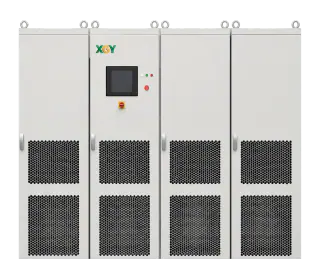
The XGY MVGS medium-voltage grid simulator is Method E built for the medium-voltage, megawatt class: direct-MV synthesis from a front-end-isolation architecture, four-quadrant operation with energy returned to the facility mains, and a programmable event library—in a current sample configuration rated 5 MVA at 13.8 kV. At quote stage, configuration review maps the test plan across all five methods, identifies the questions that genuinely require Method E, and sizes the platform to those questions rather than to an undifferentiated headline rating.
FAQ
Frequently asked questions
Which test method is best for megawatt converters?
None universally—the methods answer different questions. Endurance is commonly most efficient back-to-back; scenario exploration belongs to PHIL and scaled hardware; programmable events at real voltage and power require a suitable full-power grid simulator; long coexistence soak suits utility connection. Allocate evidence claims across the portfolio instead of selecting one method for every claim.
Can PHIL replace full-power testing?
Not for every claim. PHIL applies rich simulated grid dynamics to real hardware within the power interface's validated stability, power and bandwidth envelope, making it valuable for development and integration study. Claims that depend on rated terminal voltage, full-power thermal behaviour or protection at actual levels require an appropriately rated physical method. PHIL can identify the critical scenarios and full-power testing can confirm them.
Is back-to-back testing valid evidence for grid compliance?
It can support endurance, thermal and efficiency claims when the boundaries and measurement uncertainty are defined. By itself it does not reproduce an independent grid, so it cannot substantiate ride-through, frequency, unbalance or network-protection claims. The governing standard or agreed test specification determines the required conditions and evidence.
We own an LV source—when does the step-up route stop being enough?
It stops being sufficient when the required event cannot be reproduced at the DUT terminals within the agreed waveform tolerance and repeatability. Common constraints include fast edges, flux-asymmetric or zero-voltage events, low-frequency content, zero-sequence behaviour, grounding changes and repeated events without adequate recovery. Characterise the complete source-transformer-measurement chain against the actual event list before accepting it.
Keep exploring
Related technical resources
Related articles
Application Test Guides
How to Test a Medium-Voltage SST at Full Power
The complete SST test bench, block by block: programmable MV grid interface, regenerative DC load or battery emulator, measurement and safety layer — plus the test matrix and an RFQ checklist.
Read article
Grid Simulator Fundamentals
What Is a Grid Simulator? A Plain-English Guide
A grid simulator is a programmable AC source that reproduces grid behaviour — sags, swells, harmonics, ride-through events — for lab testing. What it does, who needs one, and how to spec it.
Read article