Network Analyzers
YNA-3674 Series Vector Network Analyzer
RF and mmWave Vector Network Analysis to 120 GHz by Model
YNA-3674 provides model-specific coverage from 10 MHz to as high as 120 GHz, with configurable measurement hardware, calibration methods and specialist software options.
Get a Quote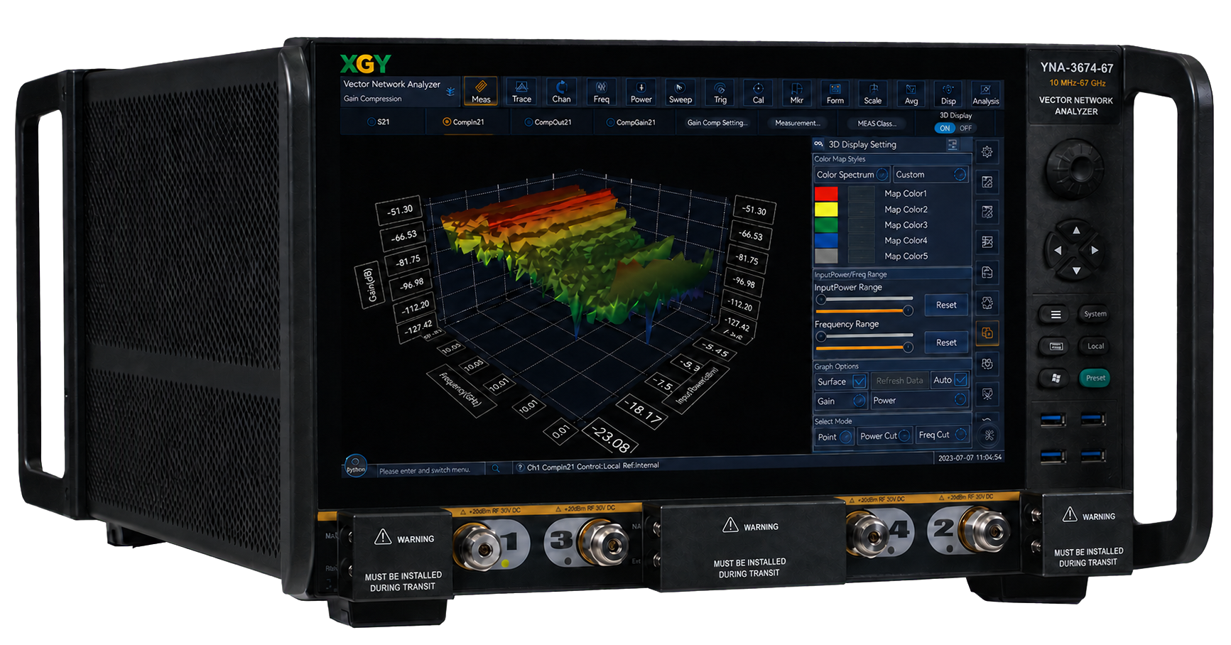
- Frequency range
- 10 MHz to 120 GHz
- By model
- IF bandwidth
- 1 Hz to 30 MHz
- Measurement points
- Up to 200,001
- Stated for the series
- Pulse resolution
- As low as 8.3 ns
- Stated for the series
Overview
YNA-3674 is a configurable vector network analyzer family for components, antennas, materials, semiconductors and high-speed interconnects. Frequency coverage starts at 10 MHz and reaches 120 GHz by model, with IF bandwidth from 1 Hz to 30 MHz and up to 200,001 measurement points.
Single-unit and extender-based configurations serve different frequency bands and connection requirements. Port count, receiver hardware, specialist measurements and calibration accessories must be selected for the chosen model and option dependencies.
Product & Measurement Gallery
Spectrum-analysis results (option -S30, listed for YNA-3674-9 to YNA-3674-67)
Simulated eye diagram
Semiconductor and chip testing
Application images show typical use settings; they do not indicate measured performance.
Materials characterization
Application images show typical use settings; they do not indicate measured performance.
Antennas and radar modules
Application images show typical use settings; they do not indicate measured performance.
High-speed interconnects
Application images show typical use settings; they do not indicate measured performance.
Microwave components and filters
Application images show typical use settings; they do not indicate measured performance.
Active and frequency-converting devices
Application images show typical use settings; they do not indicate measured performance.
Additional product details
The YNA-3674 combines RF characteristics, flexible hardware configuration and software functions for measurement tasks through one connection.
The detachable CPU module provides hard-disk storage and LAN, DP, USB, and GPIB interfaces.
Key Capabilities & Applications
Select the RF or mmWave model
Single-unit models extend through 110 GHz. YNA-3674-110-A and YNA-3674-120-A use a separate controller and 1.0 mm extender modules for 110 GHz and 120 GHz coverage respectively.
Configure the measurement task
Options include signal-integrity analysis, automatic fixture removal and time-domain measurements. Four-port, converter, noise-figure and other configurations have model-specific hardware requirements and exclusions.
Calibrate and integrate
Calibration methods include SOLT, SOLR, SSLT, SSST, TRM, TRL, electronic and waveguide calibration. The detachable CPU module provides LAN, DP, USB and GPIB connections.
All capabilities and operating conditions
Independent pulse control
4 pulse generators with pulse width and independent delay.
Test speed
Up to 30 MHz IF bandwidth supports fast testing and narrow-pulse testing.
Multi-parameter touch display
15.6-inch multi-parameter display on the same screen, with multi-touch operation.
Common applications
- Semiconductor chip testing
- Material testing
- Antenna testing
- High-speed cable testing
- Microwave component testing
- Mixer/converter vector measurement
Applications and test requirements
Semiconductor chip testing
Material testing
Antenna testing
Radar T / R components and antenna signal and transceiver module.
High-speed cable testing
Microwave component testing
Mixer/converter vector measurement
Mixer and frequency-converter measurements include amplitude response, absolute phase, and absolute delay response.
With option -023, listed for YNA-3674-9 to YNA-3674-53
Technical Specifications
| Parameter | Specification |
|---|---|
| Frequency characteristic | |
| Frequency range | 10 MHz to 120 GHzBy model |
| Frequency accuracy | ±1 × 10^-723 °C ± 3 °C |
| General characteristic | |
| IF bandwidth | 1 Hz to 30 MHz |
| Measurement points | Up to 200,001Stated for the series |
| Pulse resolution | As low as 8.3 nsStated for the series |
| General characteristic | |
| Maximum power consumption | 500 W / 600 WBy model |
| Maximum weight | 50 kg / 84 kgBy model |
Detailed performance and interface tables (12)
Frequency, harmonic suppression, port power and pulse (10 rows)
| Parameter | Specifications | Typical |
|---|---|---|
| Frequency characteristic | ||
| Frequency range | 10 MHz to 9 GHz / 14 GHz / 20 GHz / 26.5 GHz | |
| Frequency resolution | 0.1 Hz | |
| Frequency accuracy | ±1 × 10^-7 (23 °C ± 3 °C) | |
| Port harmonic suppression | ||
| Ports 1 and 3 harmonic suppression | -48 dBc (0.01 to 4 GHz); -57 dBc (4 to 14 GHz); -57 dBc (14 to 26.5 GHz) | -62 dBc (0.01 to 4 GHz); -68 dBc (4 to 14 GHz); -70 dBc (14 to 26.5 GHz) |
| Ports 2 and 4 harmonic suppression | -13 dBc (0.01 to 4 GHz); -18 dBc (4 to 14 GHz); -18 dBc (14 to 26.5 GHz) | -24 dBc (0.01 to 4 GHz); -30 dBc (4 to 14 GHz); -36 dBc (14 to 26.5 GHz) |
| Port power characteristics | ||
| Power sweep range | 33 dB (10 to 50 MHz); 35 dB (0.05 to 4 GHz); 38 dB (4 to 16 GHz); 35 dB (16 to 20 GHz); 32 dB (20 to 24 GHz); 27 dB (24 to 26.5 GHz) | 36 dB (10 to 50 MHz); 39 dB (0.05 to 4 GHz); 41 dB (4 to 16 GHz); 40 dB (16 to 20 GHz); 39 dB (20 to 24 GHz); 38 dB (24 to 26.5 GHz) |
| Maximum output power (standard configuration or four-port measurement configuration) | +13 dBm (10 to 50 MHz); +13 dBm (0.05 to 14 GHz); +13 dBm (14 to 20 GHz); +10 dBm (24 to 26.5 GHz) | +16 dBm (10 to 50 MHz); +15 dBm (0.05 to 14 GHz); +15 dBm (14 to 20 GHz); +14 dBm (24 to 26.5 GHz) |
| Maximum output power (four-port measurement, four-port programmable step attenuator, active intermodulation distortion measurement, configurable test set, and noise figure measurement options) | +10 dBm (10 to 50 MHz); +7 dBm (0.05 to 14 GHz); +5 dBm (14 to 20 GHz); +3 dBm (24 to 26.5 GHz) | +12 dBm (10 to 50 MHz); +10 dBm (0.05 to 14 GHz); +10 dBm (14 to 20 GHz); +7 dBm (24 to 26.5 GHz) |
| Pulse characteristic | ||
| Pulse width setting range | 33 ns to 70 s | 20 ns to 70 s |
| Pulse on/off ratio | 64 dB (0.01 to 4 GHz); 80 dB (4 to 26.5 GHz) | |
Models: YNA-3674-9, YNA-3674-14, YNA-3674-20, YNA-3674-26.5
Network parameter characteristics (7 rows)
| Parameter | Specifications | Typical |
|---|---|---|
| Network parameter characteristic | ||
| System dynamic range (standard or four-port measurement configuration) | 96 dB (10 to 50 MHz); 110 dB (50 to 500 MHz); 130 dB (0.5 to 4 GHz); 133 dB (4 to 14 GHz); 131 dB (14 to 20 GHz); 125 dB (20 to 26.5 GHz) | 108 dB (10 to 50 MHz); 124 dB (50 to 500 MHz); 140 dB (0.5 to 4 GHz); 140 dB (4 to 14 GHz); 133 dB (14 to 20 GHz); 128 dB (20 to 26.5 GHz) |
| System dynamic range (four-port measurement, four-port programmable step attenuator, active intermodulation distortion measurement, configurable test set, and noise figure measurement options) | 96 dB (10 to 50 MHz); 110 dB (50 to 500 MHz); 120 dB (0.5 to 4 GHz); 120 dB (4 to 14 GHz); 115 dB (14 to 20 GHz); 115 dB (20 to 26.5 GHz) | 105 dB (10 to 50 MHz); 120 dB (50 to 500 MHz); 134 dB (0.5 to 4 GHz); 134 dB (4 to 14 GHz); 128 dB (14 to 20 GHz); 122 dB (20 to 26.5 GHz) |
| Effective directivity | 48 dB (0.01 to 2 GHz); 44 dB (2 to 26.5 GHz) | 65 dB (0.01 to 2 GHz); 52 dB (2 to 26.5 GHz) |
| Effective source match | 40 dB (0.01 to 2 GHz); 31 dB (2 to 26.5 GHz) | 46 dB (0.01 to 2 GHz); 36 dB (2 to 26.5 GHz) |
| Effective load match | 47 dB (0.01 to 2 GHz); 44 dB (2 to 26.5 GHz) | 61 dB (0.01 to 2 GHz); 56 dB (2 to 26.5 GHz) |
| Reflection tracking | ±0.0150 dB (0.01 to 2 GHz); ±0.0161 dB (2 to 26.5 GHz) | ±0.0060 dB (0.01 to 2 GHz); ±0.0030 dB (2 to 26.5 GHz) |
| Transmission tracking | ±0.044 dB (10 to 50 MHz); ±0.055 dB (0.05 to 2 GHz); ±0.120 dB (2 to 9 GHz); ±0.110 dB (9 to 14 GHz); ±0.120 dB (14 to 26.5 GHz) | ±0.001 dB (10 to 50 MHz); ±0.002 dB (0.05 to 2 GHz); ±0.004 dB (2 to 9 GHz); ±0.005 dB (9 to 14 GHz); ±0.008 dB (14 to 26.5 GHz) |
Models: YNA-3674-9, YNA-3674-14, YNA-3674-20, YNA-3674-26.5
Trace noise and general characteristics (13 rows)
| Parameter | Specifications | Typical |
|---|---|---|
| Others | ||
| Amplitude trace noise dB rms (1 kHz IF bandwidth) | 0.0070 (10 to 100 MHz); 0.0020 (100 to 500 MHz); 0.0020 (0.5 to 1 GHz); 0.0020 (1 to 14 GHz); 0.0020 (14 to 22.5 GHz); 0.0030 (22.5 to 24 GHz); 0.0050 (24 to 26.5 GHz) | 0.0040 (10 to 100 MHz); 0.0017 (100 to 500 MHz); 0.0006 (0.5 to 1 GHz); 0.0006 (1 to 14 GHz); 0.0007 (14 to 22.5 GHz); 0.0008 (22.5 to 24 GHz); 0.0007 (24 to 26.5 GHz) |
| Phase trace noise deg rms (1 kHz IF bandwidth) | 0.051 (10 to 100 MHz); 0.015 (100 to 500 MHz); 0.015 (0.5 to 1 GHz); 0.015 (1 to 14 GHz); 0.042 (14 to 22.5 GHz); 0.054 (22.5 to 24 GHz); 0.054 (24 to 26.5 GHz) | 0.030 (10 to 100 MHz); 0.012 (100 to 500 MHz); 0.004 (0.5 to 1 GHz); 0.004 (1 to 14 GHz); 0.005 (14 to 22.5 GHz); 0.005 (22.5 to 24 GHz); 0.005 (24 to 26.5 GHz) |
| General characteristic | ||
| IF bandwidth | 1 Hz to 30 MHz | |
| Amplitude display resolution | 0.001 dB/div | |
| Phase display resolution | 0.001°/div | |
| Port connectors type | 3.5 mm (male), system impedance 50 Ω | |
| Measured ports | Standard: 2 ports; YNA-3674-9-400 / YNA-3674-14-400 / YNA-3674-20-400 / YNA-3674-26.5-400 option: 4 ports | |
| Peripheral interfaces | GPIB, USB, DP, and LAN | |
| Display | 15.6-inch high-resolution touch display | |
| Dimensions | Overall dimensions (W × H × D, including handles, feet and pads): 2-port: 475 × 279 × 560 mm; 4-port: 475 × 279 × 660 mm | |
| Maximum power consumption | 500 W | |
| Power supply | 50 Hz 220 V or 50 Hz/60 Hz 110 V AC | |
| Maximum weight | 50 kg | |
Models: YNA-3674-9, YNA-3674-14, YNA-3674-20, YNA-3674-26.5
Frequency, harmonic suppression, port power and pulse (10 rows)
| Parameter | Specifications | Typical |
|---|---|---|
| Frequency characteristic | ||
| Frequency range | 10 MHz to 32 GHz / 44 GHz / 50 GHz | |
| Frequency resolution | 0.1 Hz | |
| Frequency accuracy | ±1 × 10^-7 (23 °C ± 3 °C) | |
| Port harmonic suppression | ||
| Ports 1 and 3 harmonic suppression | -48 dBc (0.01 to 4 GHz); -57 dBc (4 to 14 GHz); -57 dBc (14 to 50 GHz) | -68 dBc (0.01 to 4 GHz); -70 dBc (4 to 14 GHz); -70 dBc (14 to 50 GHz) |
| Ports 2 and 4 harmonic suppression | -13 dBc (0.01 to 4 GHz); -18 dBc (4 to 14 GHz); -57 dBc (14 to 50 GHz) | -18 dBc (0.01 to 4 GHz); -31 dBc (4 to 14 GHz); -70 dBc (14 to 50 GHz) |
| Port power characteristics | ||
| Power sweep range | 37 dB (10 to 50 MHz); 38 dB (0.05 to 2 GHz); 35 dB (2 to 4 GHz); 38 dB (4 to 26.5 GHz); 37 dB (26.5 to 30 GHz); 36 dB (30 to 32 GHz); 37 dB (32 to 35 GHz); 34 dB (35 to 44 GHz); 30 dB (44 to 47 GHz); 20 dB (47 to 50 GHz) | 42 dB (10 to 50 MHz); 44 dB (0.05 to 2 GHz); 41 dB (2 to 4 GHz); 41 dB (4 to 26.5 GHz); 42 dB (26.5 to 30 GHz); 40 dB (30 to 32 GHz); 43 dB (32 to 35 GHz); 39 dB (35 to 44 GHz); 38 dB (44 to 47 GHz); 36 dB (47 to 50 GHz) |
| Maximum output power (standard configuration or four-port measurement configuration) | +12 dBm (10 to 50 MHz); +12 dBm (0.05 to 4 GHz); +12 dBm (4 to 14 GHz); +13 dBm (14 to 20 GHz); +13 dBm (20 to 26.5 GHz); +12 dBm (26.5 to 40 GHz); +9 dBm (40 to 47 GHz); +5 dBm (47 to 50 GHz) | +14 dBm (10 to 50 MHz); +13 dBm (0.05 to 4 GHz); +14 dBm (4 to 14 GHz); +14 dBm (14 to 20 GHz); +14 dBm (20 to 26.5 GHz); +15 dBm (26.5 to 40 GHz); +13 dBm (40 to 47 GHz); +10 dBm (47 to 50 GHz) |
| Maximum output power (four-port measurement, four-port programmable step attenuator, active intermodulation distortion measurement, configurable test set, and noise figure measurement options) | +9 dBm (10 to 50 MHz); +4 dBm (0.05 to 4 GHz); +4 dBm (4 to 14 GHz); +8 dBm (14 to 20 GHz); +6 dBm (20 to 26.5 GHz); +4 dBm (26.5 to 40 GHz); -1 dBm (40 to 47 GHz); -5 dBm (47 to 50 GHz) | +10 dBm (10 to 50 MHz); +7 dBm (0.05 to 4 GHz); +7 dBm (4 to 14 GHz); +9 dBm (14 to 20 GHz); +9 dBm (20 to 26.5 GHz); +7 dBm (26.5 to 40 GHz); +1 dBm (40 to 47 GHz); +0 dBm (47 to 50 GHz) |
| Pulse characteristic | ||
| Pulse width setting range | 33 ns to 70 s | 20 ns to 70 s |
| Pulse on/off ratio | 64 dB (0.01 to 4 GHz); 80 dB (4 to 50 GHz) | |
Models: YNA-3674-32, YNA-3674-44, YNA-3674-50
Network parameter characteristics (7 rows)
| Parameter | Specifications | Typical |
|---|---|---|
| Network parameter characteristic | ||
| System dynamic range (standard or four-port measurement configuration) | 89 dB (10 to 50 MHz); 106 dB (50 to 500 MHz); 130 dB (0.5 to 4 GHz); 130 dB (4 to 14 GHz); 128 dB (14 to 20 GHz); 130 dB (20 to 26.5 GHz); 125 dB (26.5 to 40 GHz); 122 dB (40 to 47 GHz); 115 dB (47 to 50 GHz) | 104 dB (10 to 50 MHz); 122 dB (50 to 500 MHz); 137 dB (0.5 to 4 GHz); 139 dB (4 to 14 GHz); 138 dB (14 to 20 GHz); 138 dB (20 to 26.5 GHz); 133 dB (26.5 to 40 GHz); 130 dB (40 to 47 GHz); 125 dB (47 to 50 GHz) |
| System dynamic range (four-port measurement, four-port programmable step attenuator, active intermodulation distortion measurement, configurable test set, and noise figure measurement options) | 83 dB (10 to 50 MHz); 100 dB (50 to 500 MHz); 114 dB (0.5 to 4 GHz); 112 dB (4 to 14 GHz); 116 dB (14 to 20 GHz); 114 dB (20 to 26.5 GHz); 112 dB (26.5 to 40 GHz); 106 dB (40 to 47 GHz); 100 dB (47 to 50 GHz) | 97 dB (10 to 50 MHz); 108 dB (50 to 500 MHz); 125 dB (0.5 to 4 GHz); 132 dB (4 to 14 GHz); 128 dB (14 to 20 GHz); 127 dB (20 to 26.5 GHz); 125 dB (26.5 to 40 GHz); 119 dB (40 to 47 GHz); 104 dB (47 to 50 GHz) |
| Effective directivity | 41 dB (0.01 to 2 GHz); 38 dB (2 to 20 GHz); 36 dB (20 to 50 GHz) | 59 dB (0.01 to 2 GHz); 54 dB (2 to 20 GHz); 47 dB (20 to 50 GHz) |
| Effective source match | 31 dB (0.01 to 2 GHz); 30 dB (2 to 20 GHz); 23 dB (20 to 50 GHz) | 45 dB (0.01 to 2 GHz); 36 dB (2 to 20 GHz); 31 dB (20 to 50 GHz) |
| Effective load match | 42 dB (0.01 to 2 GHz); 37 dB (2 to 20 GHz); 35 dB (20 to 50 GHz) | 58 dB (0.01 to 2 GHz); 55 dB (2 to 20 GHz); 51 dB (20 to 50 GHz) |
| Reflection tracking | ±0.0150 dB (0.01 to 2 GHz); ±0.0290 dB (2 to 20 GHz); ±0.0300 dB (20 to 40 GHz); ±0.0400 dB (40 to 50 GHz) | ±0.0046 dB (0.01 to 2 GHz); ±0.0022 dB (2 to 20 GHz); ±0.0020 dB (20 to 40 GHz); ±0.0065 dB (40 to 50 GHz) |
| Transmission tracking | ±0.051 dB (10 to 50 MHz); ±0.030 dB (0.05 to 2 GHz); ±0.095 dB (2 to 10 GHz); ±0.120 dB (10 to 20 GHz); ±0.200 dB (20 to 40 GHz); ±0.200 dB (40 to 50 GHz) | ±0.002 dB (10 to 50 MHz); ±0.004 dB (0.05 to 2 GHz); ±0.002 dB (2 to 10 GHz); ±0.002 dB (10 to 20 GHz); ±0.005 dB (20 to 40 GHz); ±0.002 dB (40 to 50 GHz) |
Models: YNA-3674-32, YNA-3674-44, YNA-3674-50
Trace noise and general characteristics (13 rows)
| Parameter | Specifications | Typical |
|---|---|---|
| Others | ||
| Amplitude trace noise dB rms (1 kHz IF bandwidth) | 0.2000 (10 to 50 MHz); 0.0200 (50 to 500 MHz); 0.0030 (0.5 to 1 GHz); 0.0020 (1 to 26.5 GHz); 0.0030 (26.5 to 44 GHz); 0.0040 (44 to 50 GHz) | 0.0039 (10 to 50 MHz); 0.0006 (50 to 500 MHz); 0.0005 (0.5 to 1 GHz); 0.0006 (1 to 26.5 GHz); 0.0007 (26.5 to 44 GHz); 0.0008 (44 to 50 GHz) |
| Phase trace noise deg rms (1 kHz IF bandwidth) | 1.000 (10 to 50 MHz); 0.500 (50 to 500 MHz); 0.020 (0.5 to 1 GHz); 0.020 (1 to 26.5 GHz); 0.030 (26.5 to 50 GHz) | 0.024 (10 to 50 MHz); 0.004 (50 to 500 MHz); 0.003 (0.5 to 1 GHz); 0.004 (1 to 26.5 GHz); 0.005 (26.5 to 50 GHz) |
| General characteristic | ||
| IF bandwidth | 1 Hz to 30 MHz | |
| Amplitude display resolution | 0.001 dB/div | |
| Phase display resolution | 0.001°/div | |
| Port connectors | 2.4 mm (head), system impedance 50 Ω | |
| Measured ports | Standard: 2 ports; YNA-3674-32-400 / YNA-3674-44-400 / YNA-3674-50-400 option: 4 ports | |
| Peripheral interface | GPIB interface, USB interface, DP interface, LAN interface | |
| Display | 15.6-inch high-resolution touch display | |
| Dimensions | Overall dimensions (W × H × D, including handles, feet and pads): 2-port: 475 × 279 × 560 mm; 4-port: 475 × 279 × 660 mm | |
| Maximum power consumption | 500 W | |
| Power supply | 50 Hz single-phase 220 V or 50 Hz / 60 Hz single-phase 110 V AC | |
| Maximum weight | 50 kg | |
Models: YNA-3674-32, YNA-3674-44, YNA-3674-50
Frequency, harmonic suppression, port power and pulse (10 rows)
| Parameter | Specifications | Typical |
|---|---|---|
| Frequency characteristic | ||
| Frequency range | 10 MHz to 53/67 GHz | |
| Frequency resolution | 0.1 Hz | |
| Frequency accuracy | ±1 × 10^-7 (23 °C ± 3 °C) | |
| Port harmonic suppression | ||
| Ports 1 and 3 harmonic suppression | -48 dBc (0.01 to 4 GHz); -57 dBc (4 to 14 GHz); -57 dBc (14 to 67 GHz) | -57 dBc (0.01 to 4 GHz); -70 dBc (4 to 14 GHz); -71 dBc (14 to 67 GHz) |
| Ports 2 and 4 harmonic suppression | -13 dBc (0.01 to 4 GHz); -18 dBc (4 to 14 GHz); -57 dBc (14 to 67 GHz) | -25 dBc (0.01 to 4 GHz); -32 dBc (4 to 14 GHz); -72 dBc (14 to 67 GHz) |
| Port power characteristics | ||
| Power sweep range | 35 dB (10 to 50 MHz); 38 dB (0.05 to 2 GHz); 35 dB (2 to 4 GHz); 38 dB (4 to 10 GHz); 36 dB (10 to 14 GHz); 37 dB (14 to 16 GHz); 35 dB (16 to 19 GHz); 34 dB (19 to 26.5 GHz); 33 dB (26.5 to 30 GHz); 32 dB (30 to 32 GHz); 32 dB (32 to 35 GHz); 30 dB (35 to 40 GHz); 35 dB (40 to 67 GHz) | 41 dB (10 to 50 MHz); 44 dB (0.05 to 2 GHz); 40 dB (2 to 4 GHz); 42 dB (4 to 10 GHz); 43 dB (10 to 14 GHz); 42 dB (14 to 16 GHz); 40 dB (16 to 19 GHz); 37 dB (19 to 26.5 GHz); 37 dB (26.5 to 30 GHz); 36 dB (30 to 32 GHz); 39 dB (32 to 35 GHz); 36 dB (35 to 40 GHz); 40 dB (40 to 67 GHz) |
| Maximum output power (standard configuration or four-port measurement configuration) | +10 dBm (10 to 50 MHz); +10 dBm (0.05 to 14 GHz); +12 dBm (14 to 20 GHz); +11 dBm (20 to 26.5 GHz); +10 dBm (26.5 to 30 GHz); +7 dBm (30 to 32 GHz); +9 dBm (32 to 35 GHz); +5 dBm (35 to 40 GHz); +10 dBm (40 to 67 GHz) | +16 dBm (10 to 50 MHz); +14 dBm (0.05 to 14 GHz); +16 dBm (14 to 20 GHz); +14 dBm (20 to 26.5 GHz); +13 dBm (26.5 to 30 GHz); +10 dBm (30 to 32 GHz); +12 dBm (32 to 35 GHz); +11 dBm (35 to 40 GHz); +16 dBm (40 to 67 GHz) |
| Maximum output power (four-port measurement, four-port programmable step attenuator, active intermodulation distortion measurement, configurable test set, and noise figure measurement options) | +6 dBm (10 to 50 MHz); +4 dBm (0.05 to 14 GHz); +4 dBm (14 to 20 GHz); +4 dBm (20 to 26.5 GHz); -2 dBm (26.5 to 30 GHz); -2 dBm (30 to 32 GHz); -2 dBm (32 to 35 GHz); -2 dBm (35 to 40 GHz); -2 dBm (40 to 67 GHz) | +10 dBm (10 to 50 MHz); +9 dBm (0.05 to 14 GHz); +11 dBm (14 to 20 GHz); +7 dBm (20 to 26.5 GHz); +6 dBm (26.5 to 30 GHz); +4 dBm (30 to 32 GHz); +5 dBm (32 to 35 GHz); +3 dBm (35 to 40 GHz); +4 dBm (40 to 67 GHz) |
| Pulse characteristic | ||
| Pulse width setting range | 33 ns to 70 s | 20 ns to 70 s |
| Pulse on/off ratio | 64 dB (0.01 to 4 GHz); 80 dB (4 to 67 GHz) | |
Models: YNA-3674-53, YNA-3674-67
Network parameter characteristics (7 rows)
| Parameter | Specifications | Typical |
|---|---|---|
| Network parameter characteristic | ||
| System dynamic range (standard or four-port measurement configuration) | 87 dB (10 to 50 MHz); 110 dB (50 to 500 MHz); 127 dB (0.5 to 4 GHz); 130 dB (4 to 14 GHz); 129 dB (14 to 26.5 GHz); 120 dB (26.5 to 40 GHz); 116 dB (40 to 50 GHz); 107 dB (50 to 60 GHz); 106 dB (60 to 67 GHz) | 102 dB (10 to 50 MHz); 124 dB (50 to 500 MHz); 137 dB (0.5 to 4 GHz); 142 dB (4 to 14 GHz); 138 dB (14 to 26.5 GHz); 134 dB (26.5 to 40 GHz); 128 dB (40 to 50 GHz); 118 dB (50 to 60 GHz); 116 dB (60 to 67 GHz) |
| System dynamic range (four-port measurement, four-port programmable step attenuator, active intermodulation distortion measurement, configurable test set, and noise figure measurement options) | 84 dB (10 to 50 MHz); 101 dB (50 to 500 MHz); 114 dB (0.5 to 4 GHz); 113 dB (4 to 14 GHz); 113 dB (14 to 26.5 GHz); 105 dB (26.5 to 40 GHz); 106 dB (40 to 50 GHz); 101 dB (50 to 60 GHz); 100 dB (60 to 67 GHz) | 100 dB (10 to 50 MHz); 120 dB (50 to 500 MHz); 129 dB (0.5 to 4 GHz); 130 dB (4 to 14 GHz); 128 dB (14 to 26.5 GHz); 118 dB (26.5 to 40 GHz); 115 dB (40 to 50 GHz); 112 dB (50 to 60 GHz); 106 dB (60 to 67 GHz) |
| Effective directivity | 35 dB (0.01 to 2 GHz); 41 dB (2 to 10 GHz); 38 dB (10 to 20 GHz); 37 dB (20 to 35 GHz); 37 dB (35 to 50 GHz); 34 dB (50 to 67 GHz) | 65 dB (0.01 to 2 GHz); 65 dB (2 to 10 GHz); 59 dB (10 to 20 GHz); 54 dB (20 to 35 GHz); 48 dB (35 to 50 GHz); 40 dB (50 to 67 GHz) |
| Effective source match | 34 dB (0.01 to 2 GHz); 36 dB (2 to 10 GHz); 40 dB (10 to 20 GHz); 34 dB (20 to 35 GHz); 28 dB (35 to 50 GHz); 28 dB (50 to 67 GHz) | 43 dB (0.01 to 2 GHz); 40 dB (2 to 10 GHz); 42 dB (10 to 20 GHz); 38 dB (20 to 35 GHz); 31 dB (35 to 50 GHz); 31 dB (50 to 67 GHz) |
| Effective load match | 34 dB (0.01 to 2 GHz); 40 dB (2 to 10 GHz); 36 dB (10 to 20 GHz); 35 dB (20 to 35 GHz); 36 dB (35 to 50 GHz); 33 dB (50 to 67 GHz) | 59 dB (0.01 to 2 GHz); 66 dB (2 to 10 GHz); 66 dB (10 to 20 GHz); 57 dB (20 to 35 GHz); 59 dB (35 to 50 GHz); 55 dB (50 to 67 GHz) |
| Reflection tracking | ±0.0200 dB (0.01 to 2 GHz); ±0.0110 dB (2 to 10 GHz); ±0.0330 dB (10 to 35 GHz); ±0.0200 dB (35 to 50 GHz); ±0.0310 dB (50 to 67 GHz) | ±0.0050 dB (0.01 to 2 GHz); ±0.0016 dB (2 to 10 GHz); ±0.0037 dB (10 to 35 GHz); ±0.0045 dB (35 to 50 GHz); ±0.0180 dB (50 to 67 GHz) |
| Transmission tracking | ±0.100 dB (0.01 to 2 GHz); ±0.065 dB (2 to 10 GHz); ±0.100 dB (10 to 20 GHz); ±0.110 dB (20 to 35 GHz); ±0.094 dB (35 to 50 GHz); ±0.140 dB (50 to 60 GHz); ±0.150 dB (60 to 67 GHz) | ±0.002 dB (0.01 to 2 GHz); ±0.002 dB (2 to 10 GHz); ±0.002 dB (10 to 20 GHz); ±0.003 dB (20 to 35 GHz); ±0.004 dB (35 to 50 GHz); ±0.006 dB (50 to 60 GHz); ±0.009 dB (60 to 67 GHz) |
Models: YNA-3674-53, YNA-3674-67
Trace noise and general characteristics (13 rows)
| Parameter | Specifications | Typical |
|---|---|---|
| Others | ||
| Amplitude trace noise dB rms (1 kHz IF bandwidth) | 0.0500 (10 to 50 MHz); 0.0040 (50 to 100 MHz); 0.0020 (100 to 500 MHz); 0.0030 (0.5 to 1 GHz); 0.0020 (1 to 26.5 GHz); 0.0030 (26.5 to 50 GHz); 0.0300 (50 to 67 GHz) | 0.0042 (10 to 50 MHz); 0.0030 (50 to 100 MHz); 0.0006 (100 to 500 MHz); 0.0004 (0.5 to 1 GHz); 0.0003 (1 to 26.5 GHz); 0.0009 (26.5 to 50 GHz); 0.0077 (50 to 67 GHz) |
| Phase trace noise deg rms (1 kHz IF bandwidth) | 0.400 (10 to 50 MHz); 0.020 (0.05 to 26.5 GHz); 0.030 (26.5 to 50 GHz); 0.200 (50 to 67 GHz) | 0.029 (10 to 50 MHz); 0.008 (0.05 to 26.5 GHz); 0.008 (26.5 to 50 GHz); 0.051 (50 to 67 GHz) |
| General characteristic | ||
| IF bandwidth | 1 Hz to 30 MHz | |
| Amplitude display resolution | 0.001 dB/div | |
| Phase display resolution | 0.001°/div | |
| Port connectors | 1.85 mm (head), system impedance 50 Ω | |
| Measured ports | Standard: 2 ports; YNA-3674-53-400 / YNA-3674-67-400 option: 4 ports | |
| Peripheral interface | GPIB interface, USB interface, DP interface, LAN interface | |
| Display | 15.6-inch high-resolution touch display | |
| Dimensions | Overall dimensions (W × H × D, including handles, feet and pads): 2-port: 475 × 279 × 560 mm; 4-port: 475 × 279 × 660 mm | |
| Maximum power consumption | 500 W | |
| Power supply | 50 Hz single-phase 220 V or 50 Hz / 60 Hz single-phase 110 V AC | |
| Maximum weight | 50 kg | |
Models: YNA-3674-53, YNA-3674-67
Frequency, port power, pulse and network parameters (12 rows)
| Parameter | YNA-3674-90 / YNA-3674-110 | YNA-3674-110-A / YNA-3674-120-A |
|---|---|---|
| Frequency characteristic | ||
| Frequency range | YNA-3674-90: 10 MHz to 90 GHz; YNA-3674-110: 10 MHz to 110 GHz | YNA-3674-110-A: 10 MHz to 110 GHz; YNA-3674-120-A: 10 MHz to 120 GHz |
| Frequency resolution | 1 Hz | |
| Frequency accuracy | ±1 × 10^-7 (23 °C ± 3 °C) | |
| Port harmonic suppression | -13 dBc (0.01 to 4 GHz); -25 dBc (4 to 14 GHz); -51 dBc (14 to 45 GHz); -31 dBc (45 to 55 GHz) | -13 dBc (0.01 to 3.2 GHz); -25 dBc (3.2 to 14 GHz); -31 dBc (14 to 60 GHz) |
| Port power characteristics | ||
| Maximum output power | +10 dBm (10 to 50 MHz); +10 dBm (0.05 to 2 GHz); +10 dBm (2 to 30 GHz); +5 dBm (30 to 40 GHz); +1 dBm (40 to 90 GHz); +0 dBm (90 to 110 GHz) | +5 dBm (10 to 50 MHz); +10 dBm (0.05 to 2 GHz); +8 dBm (2 to 3.2 GHz); +10 dBm (3.2 to 10 GHz); +5 dBm (10 to 24 GHz); +1 dBm (24 to 40 GHz); +3 dBm (40 to 60 GHz); +0 dBm (60 to 110 GHz); -5 dBm (110 to 120 GHz) |
| Pulse characteristic | ||
| Pulse width setting range | 33 ns to 60 s | Not specified |
| Pulse on/off ratio | 64 dB (0.01 to 4 GHz), 70 dB (4 to 90 GHz) | Not specified |
| Network parameter characteristic | ||
| System dynamic range | 70 dB (10 to 500 MHz); 110 dB (0.5 to 1 GHz); 110 dB (1 to 26.5 GHz); 107 dB (26.5 to 35 GHz); 95 dB (35 to 50 GHz); 90 dB (50 to 72 GHz); 100 dB (72 to 90 GHz); 95 dB (90 to 110 GHz) | 70 dB (10 to 500 MHz); 105 dB (0.5 to 1 GHz); 110 dB (1 to 26.5 GHz); 107 dB (26.5 to 50 GHz); 90 dB (50 to 72 GHz); 100 dB (72 to 90 GHz); 90 dB (90 to 110 GHz); 80 dB (110 to 120 GHz) |
| Effective directivity | 35 dB (0.01 to 3.2 GHz); 30 dB (3.2 to 10 GHz); 24 dB (10 to 50 GHz); 23 dB (50 to 67 GHz); 20 dB (67 to 90 GHz); 20 dB (90 to 110 GHz) | 25 dB (0.01 to 3.2 GHz); 25 dB (3.2 to 10 GHz); 20 dB (10 to 67 GHz); 22 dB (67 to 90 GHz); 20 dB (90 to 110 GHz); 20 dB (110 to 120 GHz) |
| Effective load match | 35 dB (0.01 to 3.2 GHz); 36 dB (3.2 to 10 GHz); 33 dB (10 to 26.5 GHz); 30 dB (26.5 to 50 GHz); 25 dB (50 to 67 GHz); 20 dB (67 to 90 GHz); 20 dB (90 to 110 GHz) | 29 dB (0.01 to 3.2 GHz); 30 dB (3.2 to 10 GHz); 28 dB (10 to 26.5 GHz); 30 dB (26.5 to 50 GHz); 26 dB (50 to 90 GHz); 25 dB (90 to 110 GHz); 25 dB (110 to 120 GHz) |
| Reflection tracking | ±0.050 dB (0.01 to 3.2 GHz); ±0.030 dB (3.2 to 10 GHz); ±0.033 dB (10 to 26.5 GHz); ±0.080 dB (26.5 to 50 GHz); ±0.091 dB (50 to 67 GHz); ±0.095 dB (67 to 90 GHz); ±0.099 dB (90 to 110 GHz) | ±0.080 dB (0.01 to 3.2 GHz); ±0.055 dB (3.2 to 10 GHz); ±0.090 dB (10 to 26.5 GHz); ±0.075 dB (26.5 to 50 GHz); ±0.150 dB (50 to 67 GHz); ±0.250 dB (67 to 90 GHz); ±0.300 dB (90 to 110 GHz); ±0.300 dB (110 to 120 GHz) |
| Transmission tracking | ±0.149 dB (0.01 to 3.2 GHz); ±0.090 dB (3.2 to 10 GHz); ±0.110 dB (10 to 26.5 GHz); ±0.130 dB (26.5 to 50 GHz); ±0.1500 dB (50 to 67 GHz); ±0.200 dB (67 to 90 GHz); ±0.300 dB (90 to 110 GHz) | ±0.260 dB (0.01 to 3.2 GHz); ±0.164 dB (3.2 to 10 GHz); ±0.101 dB (10 to 26.5 GHz); ±0.189 dB (26.5 to 50 GHz); ±0.343 dB (50 to 67 GHz); ±0.449 dB (67 to 90 GHz); ±0.483 dB (90 to 110 GHz); ±0.483 dB (110 to 120 GHz) |
Models: YNA-3674-90, YNA-3674-110, YNA-3674-110-A, YNA-3674-120-A
Trace noise and general characteristics (10 rows)
| Parameter | YNA-3674-90 / YNA-3674-110 | YNA-3674-110-A / YNA-3674-120-A |
|---|---|---|
| Others | ||
| Amplitude trace noise dB rms (100 Hz IF bandwidth) | 0.050 (10 to 100 MHz); 0.004 (0.1 to 26.5 GHz); 0.007 (26.5 to 50 GHz); 0.009 (50 to 90 GHz); 0.009 (90 to 110 GHz) | 0.200 (10 to 100 MHz); 0.007 (0.1 to 26.5 GHz); 0.004 (26.5 to 50 GHz); 0.007 (50 to 110 GHz); 0.009 (110 to 120 GHz) |
| General characteristic | ||
| IF bandwidth | 1 Hz to 30 MHz | |
| Port connectors | 1.0 mm (male), system impedance 50 Ω | |
| Number of measured ports | Standard: 2 ports; YNA-3674-90-400 option: 4 ports | YNA-3674-26.5 / YNA-3674-32 / YNA-3674-44 / YNA-3674-50 / YNA-3674-53 / YNA-3674-67 + YNA-3674-009: 2 ports; YNA-3674-26.5 / YNA-3674-32 / YNA-3674-44 / YNA-3674-50 / YNA-3674-53 / YNA-3674-67 + YNA-3674-010: 4 ports |
| Peripheral interface | GPIB interface, USB interface, DP interface, LAN interface | |
| Display | 15.6-inch touch screen with 1920 × 1080 high-resolution | |
| Dimensions | Overall dimensions (W × H × D, including handles, feet and pads): 2-port: 475 × 279 × 560 mm; 4-port: 475 × 279 × 660 mm | — |
| Maximum power consumption | 500 W | 600 W |
| Power supply | 50 Hz 220 V or 50 Hz / 60 Hz 110 V AC | |
| Maximum weight | 50 kg | 84 kg |
Models: YNA-3674-90, YNA-3674-110, YNA-3674-110-A, YNA-3674-120-A
Measurement functions and hardware (24 rows)
| Parameter | Specifications |
|---|---|
| Measurement functions | 21 functions, including frequency conversion device measurement. |
| Measurements | Supported measurements include S parameters, differential and balanced parameters, receiver measurements, limit testing, ripple testing, and filter-bandwidth testing. |
| Calibration methods | Supported calibration methods include SOLT, SOLR, SSLT, SSST, TRM, TRL, custom calibration components, electronic calibration, and waveguide calibration. |
| Display formats | Supported display formats include logarithmic magnitude, phase, group delay, Smith chart, linear magnitude, VSWR, real, imaginary, polar, and impedance. |
| Rear-panel bias-tee connection | Rear-panel connections include bias-tee configuration input. |
| Rear-panel reference connection | 1-10 MHz external reference input / output interface |
| Rear-panel external and intermediate-frequency connection | 5-External and intermediate frequency input interface, pulse input and output interface |
| Rear-panel automatic test and trigger connection | 7-Automatic test interface, trigger input / output interface, noise source power interface |
| Rear-panel excitation and local vibration connection | 4-excitation output and local vibration output provide flexible measurement configuration |
| Pulse generator | Built-in 4-channel pulse generator for internal source modulation, IF gate control, and output from the rear panel. The pulse width and time delay of each pulse generator can be set independently. |
| Broadband synchronous pulse test pulse width | Broadband synchronous pulse test pulse width < 42 ns |
| Pulse synchronisation | Pulse synchronization can be internal or external, with seven source-modulation modes. |
| Trigger modules | Three trigger input and output modules provide system-coordination functions. |
| Pulse measurement modes | Automatic broadband synchronous measurement and narrow-band asynchronous measurement function; Adaptive narrow-band filter to improve the narrow-pulse test capability |
| Pulse test functions | Pulse envelope test; Pulse point test |
| Mixer/converter settings | Provide comprehensive measurement setting of Mixer/Converter characteristics, support double-order primary vibration and external primary vibration source input, support multiple scanning types such as linear sweep, power sweep and segment sweep, simple setting can automatically complete the complex mixer RF, double LO, IF frequency doubling and frequency distribution, support the setting of source port power, local vibration port power, attenuation, and power sweep characteristics. |
| Frequency conversion loss and calibration | Provide the most direct and accurate mixer / Converter frequency conversion loss amplitude response measurement function. Enhance power calibration by power meter to complete the RF and IF full band calibration. |
| Non-insertable frequency-conversion devices | Dual independent source-power and receiver calibration supports non-insertable frequency-conversion devices through port separation. |
| Mixer characterization | The vector measurement analysis of mixer / Converter can complete the characterization of the mixer, which is used to determine the characteristics of the mixer and obtain the characteristics of the Converter (option -023, listed for YNA-3674-9 to YNA-3674-53). The feature characterization function serves as an independent function, and the generated mixer characterization data files can be automatically called in the vector measurement analysis. |
| Simultaneous measurement | Primary connection can simultaneously test S parameters, noise coefficient (option -003, listed for YNA-3674-9 to YNA-3674-67), noise parameters, gain compression (option YNA-3674-S26, listed for YNA-3674-9 to YNA-3674-67) and frequency conversion gain. |
| Noise-coefficient measurement dynamic range | The measurement dynamic range can reach 55 dB, which is suitable for testing of subjects with large gain. |
| Wideband source and receiver testing | Wideband testing supports dual-source and receiver operation in various phase, power, and frequency combinations, providing 20 customisable frequency ranges. This allows for measurement and analysis of parameters such as input and output power, gain, harmonic distortion, and local oscillator leakage under true differential excitation, simplifying testing of various devices such as differential amplifiers and I/Q mixers in complex scenarios. |
| Receiver and frequency combinations | User can define measurement parameters for up to eight receiver and frequency combinations. |
| Conventional S-parameter test | A single instrument can realize the conventional S parameter test |
Specifications are subject to change without notice.
— Not specified.
Models, Configuration & Compatibility
13 listed models
All model codes (13)
YNA-3674-9 · YNA-3674-14 · YNA-3674-20 · YNA-3674-26.5 · YNA-3674-32 · YNA-3674-44 · YNA-3674-50 · YNA-3674-53 · YNA-3674-67 · YNA-3674-90 · YNA-3674-110 · YNA-3674-110-A · YNA-3674-120-A
Model matrix (13)
| Model | Frequency range | Configuration |
|---|---|---|
| YNA-3674-9 | 10 MHz to 9 GHz | Single-Unit Configuration |
| YNA-3674-14 | 10 MHz to 14 GHz | Single-Unit Configuration |
| YNA-3674-20 | 10 MHz to 20 GHz | Single-Unit Configuration |
| YNA-3674-26.5 | 10 MHz to 26.5 GHz | Single-Unit Configuration |
| YNA-3674-32 | 10 MHz to 32 GHz | Single-Unit Configuration |
| YNA-3674-44 | 10 MHz to 44 GHz | Single-Unit Configuration |
| YNA-3674-50 | 10 MHz to 50 GHz | Single-Unit Configuration |
| YNA-3674-53 | 10 MHz to 53 GHz | Single-Unit Configuration |
| YNA-3674-67 | 10 MHz to 67 GHz | Single-Unit Configuration |
| YNA-3674-90 | 10 MHz to 90 GHz | Single-Unit Configuration |
| YNA-3674-110 | 10 MHz to 110 GHz | Single-Unit Configuration |
| YNA-3674-110-A | 10 MHz to 110 GHz | Extender-Based Configuration with separate controller and 1.0 mm extender modules |
| YNA-3674-120-A | 10 MHz to 120 GHz | Extender-Based Configuration with separate controller and 1.0 mm extender modules |
Model comparison (1)
Calibration accessory interface ranges (5 rows)
| Interface | Mechanical kit ranges | Two-port / four-port electronic kit range |
|---|---|---|
| N-Type, 50 Ω | DC to 18 GHz | 100 kHz to 18 GHz |
| 3.5 mm | DC to 6 GHz; DC to 9 GHz; DC to 26.5 GHz | 10 MHz to 26.5 GHz |
| 2.92 mm | — | 10 MHz to 40 GHz |
| 2.4 mm | DC to 40 GHz; DC to 50 GHz | 10 MHz to 50 GHz |
| 1.85 mm | — | 10 MHz to 67 GHz |
Calibration accessory options include two-port and four-port electronic kits. Blank mechanical cells indicate that a mechanical kit is not specified for that interface.
Options
Options (55)
| Code | Description | Models | Standard | Requires / excludes |
|---|---|---|---|---|
| YNA-3674-006 | English Version Option, English front and rear panels and an English operating system. | Not stated | Not stated | — |
| YNA-3674-007 | Linux Operating System, Configures the Linux operating system to replace the Windows operating system. | Not stated | Not stated | — |
| YNA-3674-009 | 2-Port Millimeter-Wave Test Set. Used to expand the frequency of a vector network analyzer for two-port operation. | Not stated | Not stated | YNA-3674-S20 |
| YNA-3674-010 | 4-Port Millimeter-Wave Test Set. Used for vector network analyzer frequency expansion to four-port operation. | For YNA-3674-110-A Vector Network Analyzer (10 MHz ~ 110 GHz) With Separate Controller and 1.0mm Extender Modules, Frequency-Extension Hardware, Item 4. | Not stated | YNA-3674-S20; For YNA-3674-110-A Vector Network Analyzer (10 MHz ~ 110 GHz) With Separate Controller and 1.0mm Extender Modules, Frequency-Extension Hardware, Item 4. |
| YNA-3674-011 | 110 GHz Coaxial Frequency Extender. Achieves coaxial S parameter measurement from 10 MHz to 110 GHz. | For YNA-3674-110-A Vector Network Analyzer (10 MHz ~ 110 GHz) With Separate Controller and 1.0mm Extender Modules, Frequency-Extension Hardware, Item 3: | Not stated | 2-port: YNA-3674-009 + YNA-3674-S20; For YNA-3674-110-A Vector Network Analyzer (10 MHz ~ 110 GHz) With Separate Controller and 1.0mm Extender Modules, Frequency-Extension Hardware, Item 3: YNA-3674-011 (Quantity 2) YNA-3674-011 (Quantity 4). Choose 2 modules for a 2-port configuration or 4 modules for a 4-port configuration. 4-Port Requires: the selected model's Four-Port Measurement option + YNA-3674-010 + YNA-3674-S20. |
| YNA-3674-S05 | S-Parameter Signal Integrity Analysis Function. Frequency-domain, time-domain TDR, and crosstalk signal integrity characteristics can automatically convert the graph curve into a test report. For the full range. | Not stated | Not stated | A single view completes both time domain and frequency domain test analysis, helping the user to find the source of impedance discontinuity, reflection and crosstalk. It can accurately measure the impedance characteristics of transmission lines; convenient proximal and remote crosstalk tests to test the degree of interaction between multiple transmission lines. Signal-integrity time-domain analysis provides micron-level spatial resolution for locating discontinuities in small chip-packaging tests. |
| YNA-3674-S07 | Automatic Fixture Removal Function (AFR), For automatic testing and removal of single-ended and balanced-device measuring fixtures, For the full range. | Not stated | Not stated | The fixture is usually used to connect the measured piece to a vector network analyzer, but the fixture also introduces measurement error: the automatic fixture removal function can extract, store the fixture parameters and embed the fixture, and finally obtain the real parameters of the measured parts. Using the automatic fixture removal function, the measured parts, balance parameter extraction and four-port embedding. It can effectively remove the transmission parameters, proximal crosstalk, and remote crosstalk. This feature does not require custom calibration, eliminates proximal and distal crosstalk of the differential fixture, and is suitable for test scenarios with open circuit at one end of the fixture. |
| YNA-3674-S10 | Time Domain Measurement Function, Determines and analyzes discontinuous positions in devices, fixtures, or cables, For the full range. | Not stated | Not stated | — |
| YNA-3674-S11 | Advanced Time Domain Analysis Function. For TDR time-domain impedance testing and eye-map analysis. For the full range. | Not stated | Not stated | Virtual eye-diagram analysis supports predefined pass/fail templates, jitter and noise application, pre-emphasis, and equalisation. |
| YNA-3674-S16 | True Differential Measurement Function. For real differential-mode and common-mode excitation balanced-parameter measurements. | YNA-3674-9 to YNA-3674-67 | Not stated | Requires the selected model's Four-Port Measurement and Configurable Test Set options, and YNA-3674-S28. |
| YNA-3674-S18 | Fast CW Sweep Function. Data is read immediately using the FIFO buffer method. For the full range. | Not stated | Not stated | — |
| YNA-3674-S20 | Frequency Offset Function, For frequency offset measurements, For the full range. | Not stated | Not stated | — |
| YNA-3674-S22 | Mixer/Converter Scalar Measurement. For mixer scalar parameter measurement. | YNA-3674-9 to YNA-3674-67 | Not stated | YNA-3674-S20 |
| YNA-3674-S24 | Embedded LO Frequency Converter Measurement, For embedded local-oscillator converter measurement. | YNA-3674-9 to YNA-3674-67 | Not stated | 2-port: -204 + YNA-3674-S20; 4-port: -404 + YNA-3674-S20; Either YNA-3674-S22 or YNA-3674-9-023 / YNA-3674-14-023 / YNA-3674-20-023 / YNA-3674-26.5-023 / YNA-3674-32-023 / YNA-3674-44-023 / YNA-3674-50-023 / YNA-3674-53-023 / YNA-3674-67-023 is required. |
| YNA-3674-S26 | Gain Compression Measurement. Gain compression measurement for active devices such as amplifiers. | YNA-3674-9 to YNA-3674-67 | Not stated | The gain compression measurement function completes the measurement of the linear gain, compression point gain, input power, output power, and linear input matching in the active device through one connection and one calibration. Power and receiver calibration provide compression-point input power, output power, gain, and input and output matching values. Intelligent power and frequency scanning supports multiple compression methods for different measurement scenarios. Three-dimensional views show frequency and power profiles for the measured device. |
| YNA-3674-S28 | Phase-Scan Measurement, For phase-scan measurements. | YNA-3674-9 to YNA-3674-67 | Not stated | -400 |
| YNA-3674-S29 | Differential I/Q Measurement. Measures conversion loss or gain, LO feedthrough, local-oscillator isolation, differential harmonics, total harmonic distortion, and image rejection under differential or I/Q excitation. Supports customizable phase, power, and frequency parameters. | YNA-3674-9 to YNA-3674-67 | Not stated | Requires the selected model's Four-Port Measurement option, YNA-3674-S20, and YNA-3674-S28. A single calibration performs multi-channel error correction for standard S parameters and total harmonic distortion, including ratio-measurement error, absolute-receiver measurement error, port-excitation power, and transmission and mismatch errors introduced by mechanical attenuation files between channels. Measurement parameters can be edited in an XML file, imported with one operation, and updated in real time on the parameter-selection interface. A single calibration allows simultaneous error correction for multiple channels, including standard S-parameters and differential I/Q measurements. Source and receiver calibration with port mismatch ensures dual-source output power and phase accuracy. |
| YNA-3674-9-003 / YNA-3674-14-003 / YNA-3674-20-003 / YNA-3674-26.5-003 / YNA-3674-32-003 / YNA-3674-44-003 / YNA-3674-50-003 / YNA-3674-53-003 / YNA-3674-67-003 | Noise Figure Measurement. For accurate measurement of S parameters, noise coefficient, and noise parameters. | YNA-3674-9 to YNA-3674-67 | Not stated | 2-port: -201 + -204; 4-port: -401 + -404; Two-port electronic calibrators and ordinary noise sources need to be purchased separately. Based on the cold source noise coefficient test method, the accurate noise coefficient and noise parameter test can be conducted. By constructing the advanced noise correlation matrix model and combining with the precise S parameter calibration of the vector network analyzer, it is suitable for the accurate test of the measured parts with the lower noise coefficient. Noise embedding and de-embedding support noise-figure testing of non-standard-interface devices, including microwave chips, and remove the effect of mismatch between the tested part and the test equipment. |
| YNA-3674-9-008 / YNA-3674-14-008 / YNA-3674-20-008 / YNA-3674-26.5-008 / YNA-3674-32-008 / YNA-3674-44-008 / YNA-3674-50-008 / YNA-3674-53-008 / YNA-3674-67-008 | Pulse Measurement, For the S parameter measurement in the pulse state, ports 1 and 3 output the pulse modulation signal. | YNA-3674-9 to YNA-3674-67 | Not stated | Sweeping pulse S parameter test. |
| YNA-3674-26.5-018 / YNA-3674-32-018 / YNA-3674-44-018 / YNA-3674-50-018 / YNA-3674-53-018 | Multi-port extension controller | YNA-3674-26.5 to YNA-3674-53 | Not stated | — |
| YNA-3674-9-023 / YNA-3674-14-023 / YNA-3674-20-023 / YNA-3674-26.5-023 / YNA-3674-32-023 / YNA-3674-44-023 / YNA-3674-50-023 / YNA-3674-53-023 | Mixer/Converter Vector Measurement, For mixer-based vector parameter measurement | YNA-3674-9 to YNA-3674-53 | Not stated | -400 + -404 + YNA-3674-S20 |
| YNA-3674-9-201 / YNA-3674-14-201 / YNA-3674-20-201 | 2-port programmable step attenuator, 2-70 dB step attenuators for source path and 2 step attenuators, 35 dB for receiver path. | YNA-3674-9 to YNA-3674-20 | Not stated | -204 |
| YNA-3674-26.5-201 | 2-port programmable step attenuator, 2-70 dB step attenuators for source path and 2-35 dB step attenuators for receiver path. | YNA-3674-26.5 | Not stated | -204 |
| YNA-3674-32-201 / YNA-3674-44-201 / YNA-3674-50-201 | 2-port programmable step attenuator, 2-60 dB step attenuators for source path and 2-35 dB step attenuators for receiver path. | YNA-3674-32 to YNA-3674-50 | Not stated | -204 |
| YNA-3674-53-201 | 2-port programmable step and 2-50 dB programmed step attenuators for receiver attenuator path, 2-50 dB programmed step attenuators for source path. | YNA-3674-53 | Not stated | -204 |
| YNA-3674-67-201 | 2-port programmable step attenuator, 2-50 dB step attenuators for source path and 2-50 dB step attenuators for receiver path. | YNA-3674-67 | Not stated | -204 |
| YNA-3674-9-203 / YNA-3674-14-203 / YNA-3674-20-203 / YNA-3674-26.5-203 / YNA-3674-32-203 / YNA-3674-44-203 / YNA-3674-53-203 / YNA-3674-67-203 | 2-port 500 Hz low-frequency expansion | YNA-3674-9 to YNA-3674-44, YNA-3674-53, YNA-3674-67 | Optional | -204; Excludes -205 |
| YNA-3674-50-203 | 2-Port 500 Hz Low-Frequency Expansion. Extends the two-port model test frequency to 500 Hz. | YNA-3674-50 | Optional | -204; Excludes -205 |
| YNA-3674-9-204 / YNA-3674-14-204 / YNA-3674-20-204 / YNA-3674-26.5-204 / YNA-3674-32-204 / YNA-3674-44-204 / YNA-3674-50-204 / YNA-3674-53-204 / YNA-3674-67-204 | Configurable test set panel jumper, and can use a , b, r1, r2 receiver | YNA-3674-9 to YNA-3674-67 | Not stated | — |
| YNA-3674-9-205 / YNA-3674-14-205 / YNA-3674-20-205 / YNA-3674-26.5-205 / YNA-3674-44-205 / YNA-3674-50-205 / YNA-3674-53-205 | 2-port T-Type bias-tees the port output DC offset voltage. | YNA-3674-9 to YNA-3674-26.5, YNA-3674-44 to YNA-3674-53 | Not stated | -201 + -204; Excludes -203 |
| YNA-3674-32-205 | 2-port T-Type bias-tees 2 T-Type biasing devices are configured internally for 30 the port output DC offset voltage. | YNA-3674-32 | Not stated | -201 + -204; Excludes -203 |
| YNA-3674-67-205 | 2-Port T-Type Bias Tees, Two T-type biasing devices are configured internally for the port output DC offset voltage | YNA-3674-67 | Not stated | -201 + -204; Excludes -203 |
| YNA-3674-9-400 | 4-Port Measurement. Dual-source excitation four-port vector network analyzer configuration with a frequency range of 10 MHz to 9 GHz. | YNA-3674-9 | Optional | — |
| YNA-3674-14-400 | 4-Port Measurement, Dual-source excitation four-port vector network analyzer configuration with a frequency range of 10 MHz to 14 GHz. | YNA-3674-14 | Optional | — |
| YNA-3674-20-400 | 4-port measurement configuration with a frequency range of 10 MHz to 20 GHz. | YNA-3674-20 | Optional | — |
| YNA-3674-26.5-400 | 4-port measurement analyzer configuration with frequency range 10 MHz to 26.5 GHz. | YNA-3674-26.5 | Optional | — |
| YNA-3674-32-400 | 4-port measurement analyzer configuration with a frequency range of 10 MHz to 32 GHz. | YNA-3674-32 | Optional | — |
| YNA-3674-44-400 | 4-Port Measurement, Dual-source excitation four-port vector network analyzer configuration with a frequency range of 10 MHz to 44 GHz. | YNA-3674-44 | Optional | — |
| YNA-3674-50-400 | 4-Port Measurement. Dual-source excitation four-port vector network analyzer configuration with a frequency range of 10 MHz to 50 GHz. | YNA-3674-50 | Optional | — |
| YNA-3674-53-400 | 4-port measurement analyzer configuration with a frequency range of 10 MHz to 53 GHz. | YNA-3674-53 | Optional | — |
| YNA-3674-67-400 | 4-port measurement analyzer configuration with a frequency range of 10 MHz to 67 GHz. | YNA-3674-67 | Optional | — |
| YNA-3674-90-400 | 4-Port Measurement Option, Dual-source excitation four-port vector network analyzer configuration with a frequency range of 10 MHz to 90 GHz. | YNA-3674-90 | Optional | — |
| YNA-3674-9-401 / YNA-3674-14-401 / YNA-3674-20-401 / YNA-3674-26.5-401 | 4-port programmable step attenuator, 4-70 dB step attenuators for source path and 4 step attenuators, 35 dB for receiver path. | YNA-3674-9 to YNA-3674-26.5 | Not stated | -400 + -404 |
| YNA-3674-32-401 / YNA-3674-44-401 / YNA-3674-50-401 | 4-port programmable step attenuator, 4-60 dB step attenuators for source path and 4 step attenuators, 35 dB for receiver path. | YNA-3674-32 to YNA-3674-50 | Not stated | -400 + -404 |
| YNA-3674-53-401 | 4-port programmable and 4-50 dB programmed step attenuators for receiver step attenuator path, 4-50 dB programmed step attenuators for source path. | YNA-3674-53 | Not stated | -400 + -404 |
| YNA-3674-67-401 | 4-port programmable step attenuator, 4-50 dB step attenuators for source path and 4-50 dB step attenuators for receiver path. | YNA-3674-67 | Not stated | -400 + -404 |
| YNA-3674-14-402 / YNA-3674-20-402 / YNA-3674-26.5-402 / YNA-3674-32-402 / YNA-3674-50-402 / YNA-3674-53-402 / YNA-3674-67-402 | Active Intermodulation Distortion Measurement, For active intermodulation distortion signal measurement | YNA-3674-14 to YNA-3674-32, YNA-3674-50 to YNA-3674-67 | Not stated | -400 + -404 + YNA-3674-S20 |
| YNA-3674-9-403 / YNA-3674-53-403 | 4-port 500 Hz low-frequency expansion | YNA-3674-9, YNA-3674-53 | Optional | -400 + -404; -405 cannot be configured at the same time. |
| YNA-3674-14-403 / YNA-3674-26.5-403 / YNA-3674-50-403 | 4-port 500 Hz low-frequency expansion | YNA-3674-14, YNA-3674-26.5, YNA-3674-50 | Optional | -400 + -404; Excludes -405 |
| YNA-3674-20-403 / YNA-3674-32-403 / YNA-3674-44-403 / YNA-3674-67-403 | 4-Port 500 Hz Low-Frequency Expansion. Extends the four-port model test frequency to 500 Hz. | YNA-3674-20, YNA-3674-32, YNA-3674-44, YNA-3674-67 | Optional | -400 + -404; Excludes -405 |
| YNA-3674-9-404 / YNA-3674-14-404 / YNA-3674-20-404 / YNA-3674-26.5-404 / YNA-3674-32-404 / YNA-3674-44-404 / YNA-3674-50-404 / YNA-3674-53-404 / YNA-3674-67-404 | Configurable test set panel jumper, and can independently use a , b, c, d, r1, r2, r3, r4 receivers. | YNA-3674-9 to YNA-3674-67 | Not stated | -400 |
| YNA-3674-14-405 / YNA-3674-20-405 / YNA-3674-26.5-405 / YNA-3674-32-405 / YNA-3674-67-405 | 4-port t type bias-tees the port output DC offset voltage. | YNA-3674-14 to YNA-3674-32, YNA-3674-67 | Not stated | -400 + -401 + -404; Excludes -403 |
| YNA-3674-44-405 | 4-port t type bias-tees for the port output DC offset voltage. | YNA-3674-44 | Not stated | -400 + -401 + -404; Excludes -403 |
| YNA-3674-50-405 | 4-port t type bias-tees | YNA-3674-50 | Not stated | -400 + -401 + -404; Excludes -403 |
| YNA-3674-9-S30 / YNA-3674-14-S30 / YNA-3674-20-S30 / YNA-3674-26.5-S30 / YNA-3674-32-S30 / YNA-3674-44-S30 / YNA-3674-50-S30 / YNA-3674-53-S30 / YNA-3674-67-S30 | Spectrum Analysis Function, Used to provide a multichannel spectrum testing function. | YNA-3674-9 to YNA-3674-67 | Not stated | Each vector-network-analyzer port can measure the input and output spectrum and locate stray spectra and harmonics at a small resolution bandwidth. Complete ratio and absolute measurement error correction technology can provide more accurate measurement results. The marker of the spectrum measurement function can provide in-band power, power spectral density, occupied bandwidth, adjacent power ratio and other indicators, and one-click setting and real-time update. Stray and harmonic positioning measurement. |
Standard delivery contents
- Power cord assembly (×1) — Standard three-core power cord
- USB mouse (×1)
- Quick operation guide (×1)
- Certificate of conformity (×1)
- Aluminum alloy box (×1) — For transportation
Accessories
Accessories (73)
| Code | Description | Models | Note |
|---|---|---|---|
| YNA-3674-041 | 1 mm coaxial extender is 1.2m module | Not stated | Frequency-Extension Cables |
| YNA-3674-042 | Millimeter-Wave Test Set-to-Waveguide Frequency Extender Bundle Cable. Interconnects the millimeter-wave test set and waveguide frequency extender modules. A 2-port configuration requires 2 cables; a 4-port configuration requires 4 cables. | Not stated | Frequency-Extension Cables |
| YNA-3674-043 | Frequency extension frequency module. System cable | Not stated | Frequency-Extension Cables |
| YNA-3674-044 | Frequency extension frequency module. System cable | Not stated | Frequency-Extension Cables |
| YNA-3674-045 | Frequency extension frequency module. System cable | Not stated | Frequency-Extension Cables |
| YNA-3674-110-046 | 1.0 mm Coaxial Cable Set, 100 mm, One 1.0 mm male-to-female coaxial cable and one 1.0 mm female-to-female coaxial cable, Length: 100 mm. | Not stated | 1.0 mm coaxial cable sets |
| YNA-3674-110-047 | 1.0 mm Coaxial Cable Set, 200 mm, One 1.0 mm male-to-female coaxial cable and one 1.0 mm female-to-female coaxial cable, Length: 200 mm. | Not stated | 1.0 mm coaxial cable sets |
| YNA-3674-110-048 | 1.0 mm Coaxial Cable Set, 300 mm, One 1.0 mm male-to-female coaxial cable and one 1.0 mm female-to-female coaxial cable, Length: 300 mm. | Not stated | 1.0 mm coaxial cable sets |
| YNA-3674-061 | Extension table for test desktop extension for the test, length and width =500 mm * 350 mm. | Not stated | — |
| YNA-3674-062 | Rack-Mount Kit, Dedicated kit installed in the cabinet. | Not stated | — |
| YNA-3674-063 | Paper User Manual, Detailed user manual in paper form. | Not stated | — |
| 31101 | N-Type 50 ohm mechanical calibration for VNA calibration (DC~18 GHz) | Not stated | Mechanical calibration |
| 31121A | 3.5 mm mechanical calibration for VNA calibration (DC~6 GHz) | Not stated | Mechanical calibration |
| 31121 | 3.5 mm mechanical calibration for VNA calibration (DC~26.5 GHz) | Not stated | Mechanical calibration |
| 20202 | 3.5 mm mechanical calibration for VNA calibration (DC~9 GHz) | Not stated | Mechanical calibration |
| 31123 | 2.4 mm mechanical calibration for VNA calibration (DC~40 GHz) | Not stated | Mechanical calibration |
| 31123A | 2.4 mm mechanical calibration for VNA calibration (DC~50 GHz) | Not stated | Mechanical calibration |
| 20209LB | 1.82 mm mechanical calibration for VNA calibration (DC~67 GHz) | Not stated | Mechanical calibration |
| 20402D | N-Type 2-Port Electronic Calibration Kit. For VNA calibration from 100 kHz to 18 GHz. | Not stated | Two-Port Electronic Calibration Kits |
| 20402E | 3.5 mm 2-Port Electronic Calibration Kit, For VNA calibration from 10 MHz to 26.5 GHz. | Not stated | Two-Port Electronic Calibration Kits |
| 20402F | 2.92 mm 2-Port Electronic Calibration Kit, For VNA calibration from 10 MHz to 40 GHz. | Not stated | Two-Port Electronic Calibration Kits |
| 20402H | 2.4 mm 2-Port Electronic Calibration Kit, For VNA calibration from 10 MHz to 50 GHz. | Not stated | Two-Port Electronic Calibration Kits |
| 20402L | 1.85 mm 2-Port Electronic Calibration Kit, For VNA calibration from 10 MHz to 67 GHz. | Not stated | Two-Port Electronic Calibration Kits |
| 20404D | N-Type 4-Port Electronic Calibration Kit. For VNA calibration from 100 kHz to 18 GHz. | Not stated | Four-Port Electronic Calibration Kits |
| 20404E | 3.5 mm 4-Port Electronic Calibration Kit, For VNA calibration from 10 MHz to 26.5 GHz. | Not stated | Four-Port Electronic Calibration Kits |
| 20404F | 2.92 mm 4-Port Electronic Calibration Kit, For VNA calibration from 10 MHz to 40 GHz. | Not stated | Four-Port Electronic Calibration Kits |
| 20404H | 2.4 mm 4-Port Electronic Calibration Kit, For VNA calibration from 10 MHz to 50 GHz. | Not stated | Four-Port Electronic Calibration Kits |
| 20404L | 1.85 mm 4-Port Electronic Calibration Kit. For VNA calibration from 10 MHz to 67 GHz. | Not stated | Four-Port Electronic Calibration Kits |
| FB0HA0HB025.0 | Phase stable cable, testing port (3.5 mm -male) 3.5 mm gore test cable | YNA-3674-9 to YNA-3674-26.5 | Phase-stable test cables |
| FB0HA0HC025.0 | Phase stable cable, testing port (3.5 mm -female) 3.5 mm gore test cable | YNA-3674-9 to YNA-3674-26.5 | Phase-stable test cables |
| 87308 | Phase stable cable, testing port (3.5 mm -male) 3.5 mm test cable | YNA-3674-9 to YNA-3674-26.5 | Phase-stable test cables |
| 87308A | Phase stable cable, testing port (test end 3.5 mm -female), 3.5 mm test cable | YNA-3674-9 to YNA-3674-26.5 | Phase-stable test cables |
| FE0BN0BM025.0 | Phase stable cable, testing port (2.4 mm -male) 2.4 mm gore test cable | YNA-3674-32 to YNA-3674-50 | Phase-stable test cables |
| FE0BN0BL025.0 | Phase stable cable, testing port (2.4 mm -female) 2.4 mm gore test cable | YNA-3674-32 to YNA-3674-50 | Phase-stable test cables |
| FE0BN0AH025.0 | Phase stable cable, testing port (N-Type) 2.4 mm-N-Type gore | YNA-3674-32 to YNA-3674-50 | Phase-stable test cables |
| FE0BN0AL025.0 | Phase stable cable, testing port (N-Type -female at the test end) the 2.4 mm-N-Type | YNA-3674-32 to YNA-3674-50 | Phase-stable test cables |
| FE0BN0HB025.0 | Phase stable cable, testing port (3.5 mm -male) 2.4 mm-3.5mm gore | YNA-3674-32 to YNA-3674-50 | Phase-stable test cables |
| FE0BN0HC025.0 | Phase stable cable, testing port (test end 3.5 mm -female) 2.4 mm-3.5mm gore | YNA-3674-32 to YNA-3674-50 | Phase-stable test cables |
| FE0BN0HR025.0 | Phase stable cable, testing port (test end 2.92 mm -male) 2.4 mm-2.92mm gore | YNA-3674-32 to YNA-3674-50 | Phase-stable test cables |
| 87308HA | Phase stable cable, testing port (test end 2.4 mm -female), 2.4 mm test cable | YNA-3674-32 to YNA-3674-50 | Phase-stable test cables |
| 87308HB | Phase stable cable, testing port (2.4 mm -male) 2.4 mm test cable | YNA-3674-32 to YNA-3674-50 | Phase-stable test cables |
| FF0CN0CM025.0 | Phase stable cable, testing port (1.85 mm -male) 1.85 mm gore test | YNA-3674-53, YNA-3674-67 | Phase-stable test cables |
| FF0CN0CL025.0 | Phase stable cable, testing port (test end 1.85 mm -female), 1.85 mm gore test | YNA-3674-53, YNA-3674-67 | Phase-stable test cables |
| 87302NN | 1.85 mm Phase-Stable Test Cable, female test end. | Not stated | Phase-stable test cables |
| 87302NM | Phase stable cable, testing port (1.85 mm -male) | Not stated | Phase-stable test cables |
| 87233C | USB cw power sensor 8 kHz-12 GHz, -70 dBm-+20 dBm USB cw power sensor | Not stated | USB power sensors |
| 87233D | USB CW Power Sensor, 10 MHz to 18 GHz, -70 dBm to +20 dBm. | Not stated | USB power sensors |
| 87233E | USB CW Power Sensor, 50 MHz to 26.5 GHz, -70 dBm to +20 dBm. | Not stated | USB power sensors |
| 87233F | USB CW Power Sensor, 50 MHz to 40 GHz, -70 dBm to +20 dBm. | Not stated | USB power sensors |
| 87233L | USB CW Power Sensor, 50 MHz to 67 GHz, -55 dBm to +20 dBm. | Not stated | USB power sensors |
| 87235B | USB Average Power Sensor, 8 kHz to 8 GHz, -70 dBm to +26 dBm. | Not stated | USB power sensors |
| 87235C | USB Average Power Sensor, 10 MHz-8 GHz, -60 dBm to +23 dBm. | Not stated | USB power sensors |
| 87235D | USB Average Power Sensor, 10 MHz to 18 GHz, -70 dBm to +26 dBm. | Not stated | USB power sensors |
| 87235F | USB Average Power Sensor, 10 MHz to 33 GHz, -65 dBm to +26 dBm. | Not stated | USB power sensors |
| 87235FA | USB Average Power Sensor, 10 MHz to 40 GHz, -65 dBm to +26 dBm. | Not stated | USB power sensors |
| 87235H | USB Average Power Sensor, 10 MHz to 50 GHz, -65 dBm to +23 dBm. | Not stated | USB power sensors |
| 87235L | USB Average Power Sensor, 50 MHz to 67 GHz, -60 dBm to +23 dBm. | Not stated | USB power sensors |
| 16613DA | BNC noise source 10 MHz-18 GHz, ENR 5 dB-8 dB BNC interface | Not stated | BNC Noise Sources |
| 16613DB | BNC noise source 10 MHz-18 GHz, ENR 14 dB-17 dB traditional noise | Not stated | BNC Noise Sources |
| 16613EA | BNC noise source 10 MHz-26.5 GHz, ENR 5 dB-8 dB source | Not stated | BNC Noise Sources |
| 16613EB | BNC Noise Source, 10 MHz to 26.5 GHz, ENR 12 dB to 17 dB. | Not stated | BNC Noise Sources |
| 16613FB | BNC Noise Source, 10 MHz to 40 GHz, ENR 12 dB to 19 dB. | Not stated | BNC Noise Sources |
| 16615DA | USB noise source 10 MHz-18 GHz, ENR 5 dB-8 dB USB noise source | Not stated | USB noise sources |
| 16615DB | USB Noise Source, 10 MHz to 18 GHz, ENR 14 dB to 17 dB. | Not stated | USB noise sources |
| 16615EA | USB Noise Source, 10 MHz to 26.5 GHz, ENR 5 dB to 8 dB. | Not stated | USB noise sources |
| 16615EB | USB Noise Source, 10 MHz to 26.5 GHz, ENR 12 dB to 17 dB. | Not stated | USB noise sources |
| 16615FB | USB Noise Source, 10 MHz to 40 GHz, ENR 12 dB to 19 dB. | Not stated | USB noise sources |
| 16615HB | USB Noise Source, 10 MHz to 50 GHz, ENR 10 dB to 19 dB. | Not stated | USB noise sources |
| 16615LC | USB Noise Source, 10 MHz to 67 GHz, ENR 7 dB to 23 dB. | Not stated | USB noise sources |
| 87601 | Microwave coaxial adapter package (N-Type interface converted to 3.5 mm, assistant (type-n) 2.4 mm interface, etc.) | Not stated | Microwave coaxial adapters |
| 87601A | Microwave coaxial adapter package (3.5 mm interface converted to N-Type, assistant (3.5 mm) 2.4 mm interface, etc.) | Not stated | Microwave coaxial adapters |
| 87601B | Microwave coaxial adapter package (2.92 mm interface converted to 2.4 mm assistant (2.92 mm) interface, etc.) | Not stated | Microwave coaxial adapters |
| 87601C | 2.4 mm Microwave Coaxial Adapter Set, Converts 2.4 mm to N-Type, 3.5 mm, 2.92 mm, 1.85 mm, and related interfaces. | Not stated | Microwave coaxial adapters |
Control interfaces and software
The detachable CPU module provides hard-disk storage and LAN, DP, USB and GPIB interfaces. Rear-panel connections include 10 MHz external reference input/output, external and IF inputs, pulse input/output, bias-tee configuration input, trigger input/output and noise-source power. Supported calibration methods include SOLT, SOLR, SSLT, SSST, TRM, TRL, custom calibration components, electronic calibration and waveguide calibration.
LAN · USB · GPIB · External reference
Technical Resources
Selection guidance
Format: Single unit, or extender-based with separate controller (YNA-3674-110-A/-120-A)
Coverage: 10 MHz to 120 GHz standard, by model; 500 Hz low-frequency expansion with option -203 (2-port) or -403 (4-port), models to 67 GHz
Best for: Semiconductor chip, material, antenna, high-speed cable and microwave component measurement where one instrument must cover the whole band.
Compare products in the Network Analyzers categorySend the operating envelope, configuration and acceptance evidence you need; the quotation confirms model, options and delivery documentation.