
In brief
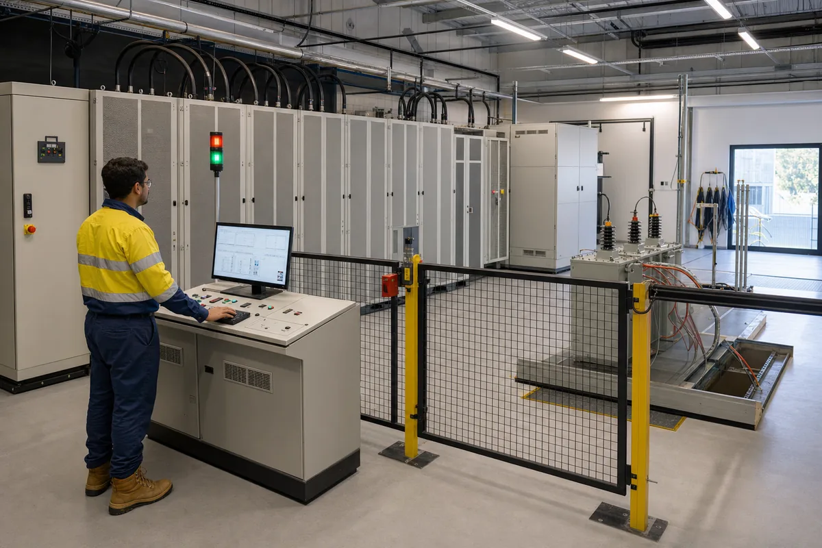
A grid simulator is a programmable AC power source that reproduces the behaviour of an electricity grid — voltage sags and swells, frequency shifts, harmonics, unbalance and fault ride-through events — so that grid-connected equipment can be tested against realistic conditions in a laboratory instead of on the live network. Four-quadrant units can also act as a regenerative load, absorbing power from the device under test and returning that energy to the facility mains.
Key takeaways
- A grid simulator replaces the utility grid with a controllable, repeatable laboratory source, so disturbances can be created on demand instead of waited for.
- The step up from an ordinary programmable AC source is the disturbance library: ride-through profiles, harmonics, unbalance and frequency events, executed as programmed sequences.
- Four-quadrant designs both source and sink power; absorbed energy is returned to the facility mains rather than burned as heat.
- Sizing comes down to ten parameters — voltage class, power rating, quadrants, disturbance library, harmonic order, RoCoF, dynamic response, interfaces, cooling and protection boundary.
- Low-voltage units cover most component and small-inverter work; megawatt-scale, medium-voltage devices need the boundary tested at medium voltage.
Why can’t you just test on the real grid?
The utility grid is the environment your product will eventually live in, so connecting to it for testing sounds like the most honest possible test. In practice it fails on three counts.
First, the events you most need to test are the ones the grid delivers least often. A low-voltage ride-through requirement asks how your inverter behaves during a deep voltage dip lasting a few hundred milliseconds. On a healthy grid, that event might occur a handful of times a year, at unpredictable moments, with whatever depth and duration the fault happens to produce. You cannot schedule certification evidence around lightning strikes.
Second, real-grid testing is not repeatable. Engineering validation depends on running the same stimulus before and after a design change and comparing the response. Two natural voltage dips are never identical, so a “pass” after a firmware update proves little about the update itself.
Third, at megawatt scale the risk flows both ways. A converter that misbehaves during commissioning can trip protection, distort power quality for neighbouring loads, and turn a test day into an incident report. Network operators reasonably restrict what you may deliberately do to their grid.
A grid simulator resolves all three problems at once: events are created on demand, executed identically every time, and contained inside a laboratory protection boundary. The trade-off is that the simulator itself must be engineered to behave like a grid — which is what the rest of this guide unpacks.
Grid simulator, programmable AC source, AC load — what’s the difference?
Three product categories overlap in this space, and vendors do not use the terms consistently. The table below is the practical distinction most test engineers work with.
| Term | What it does in practice | Typical use |
|---|---|---|
| Programmable AC source | Delivers clean, adjustable AC power: settable voltage, frequency and phase | Powering up equipment, steady-state and range testing |
| AC electronic load | Absorbs AC power under programmed conditions (constant resistance, current or power) | Loading sources such as inverters, UPS and generators |
| Grid simulator | An AC source with a grid-disturbance library — sags, swells, frequency events, harmonics, unbalance — often with four-quadrant sink capability | Compliance, robustness and grid-interaction testing |
The phrase grid emulator is generally interchangeable with grid simulator; in research settings it sometimes implies a real-time simulation model coupled to the power amplifier, as used in power-hardware-in-the-loop work. If a datasheet uses the word emulator, check whether it means a disturbance library, a real-time interface, or both.
What does “four-quadrant” mean?
| Active-power direction | Reactive-power direction | Test-source role |
|---|---|---|
| Source active power | Supply reactive power | Emulate a grid supporting an exporting or inductive operating point |
| Sink active power | Supply reactive power | Absorb DUT export while supplying reactive power |
| Sink active power | Absorb reactive power | Absorb both active export and capacitive reactive power |
| Source active power | Absorb reactive power | Power the DUT while absorbing capacitive reactive power |
Plot active power on one axis and reactive power on the other and you get four quadrants. A conventional power supply lives in the quadrants where it delivers power. A four-quadrant grid simulator operates in all four: it can deliver active and reactive power like a grid, and it can absorb active and reactive power like a load.
That matters because most modern devices under test are themselves bidirectional. An energy-storage power conversion system charges in one test and discharges in the next; a solar inverter exports power that has to go somewhere. A four-quadrant simulator absorbs that exported power, and in regenerative designs the absorbed energy is returned to the facility mains rather than dissipated as heat. For megawatt-scale endurance testing, the difference shows up directly in the electricity bill and in the cooling plant the lab must install — a topic covered in depth in our regenerative-load guide.
One citable fact worth pinning down: a four-quadrant grid simulator can act as programmable source and regenerative sink in the same test bench, which is why a single platform can cover both grid-simulation and load-simulation roles.
What grid events can a grid simulator program?
The disturbance library is the heart of the category. Five families cover most test plans.
Voltage ride-through events
LVRT, HVRT and ZVRT profiles are voltage-versus-time trajectories the device under test must survive without tripping. Grid codes worldwide define these envelopes; the simulator’s job is to execute the programmed dip or swell with a clean, fast edge and hold the profile precisely. The current MVGS Series medium-voltage grid simulator selection guide specifies voltage rise and fall time below one millisecond for that platform, subject to the selected configuration and measurement conditions. That response class is what makes millisecond-scale ride-through edges reproducible. The applicable project requirement still defines the actual trajectory and tolerance.
Frequency events and RoCoF
High-renewables grids can exhibit faster frequency swings because less rotating mass resists change. Test plans therefore include frequency ramps at a defined rate of change of frequency (RoCoF). The current MVGS selection guide lists a standard 30 to 70 Hz frequency range and programmable RoCoF above 5 Hz per second; the project requirement and final configuration determine the trajectory that must actually be delivered.
Harmonics and inter-harmonics
Immunity testing injects distortion deliberately. The current MVGS selection guide lists programmable harmonic generation through the 50th order plus non-integer inter-harmonics. The useful question is not only the highest order: an RFQ should also state required amplitude, phase, load condition, bandwidth and evidence tolerance for each programmed component.
Unbalance and single-phase events
With fully independent three-phase control, each phase’s amplitude and angle can be set separately — enabling three-phase unbalance and single-phase fault scenarios that stress the control loops and protection of the device under test.
Long-duration source and sink cycling
Beyond discrete events, endurance plans cycle the device under test across its power envelope for hours or days. This is where four-quadrant regeneration changes the economics of the test programme.
What evidence makes a grid-simulator test repeatable?
A programmed event is not evidence by itself. A defensible result ties five records to the same timebase: the requested profile, the waveform measured at the device-under-test terminals, the DUT response, the source and protection status, and the exact configuration used for the run. Without the measured-terminal trace, a saved sequence proves only what the controller was asked to do, not what the DUT received. Without the DUT state and protection log, the waveform proves a disturbance occurred but not how the equipment responded.
The minimum evidence package therefore has a predictable shape:
| Evidence record | Why it is needed |
|---|---|
| Sequence name, version and parameter set | Makes the stimulus reproducible after firmware or hardware changes |
| Time-aligned terminal voltage and current | Confirms the delivered depth, duration, edge and per-phase condition |
| DUT operating state, alarms and trip cause | Connects electrical behaviour to the equipment’s control decision |
| Simulator status, limits and protection events | Shows whether the source clipped, current-limited or aborted the profile |
| Calibration references and channel configuration | Defines the measurement uncertainty and prevents channel ambiguity |
| Pass/fail criterion and decision rule | Separates an engineering observation from an acceptance result |
This is also the practical distinction between a demonstration and a qualification-oriented campaign. IEEE 1547 defines interconnection and interoperability requirements for distributed energy resources, while IEEE 1547.1 defines conformance test procedures for those functions. A grid simulator can create the required electrical conditions, but the applicable standard, laboratory process, calibrated measurement chain and decision rule determine whether the resulting evidence is acceptable. The instrument does not certify the DUT.
What devices get tested on a grid simulator?
Anything that connects to the grid through power electronics is a candidate. The most common device-under-test families today are: energy-storage power conversion systems (PCS) and battery energy storage systems; solar inverters, from string units at low voltage to utility-scale central inverters moving toward medium-voltage connection; wind-turbine converters; UPS systems, including the medium-voltage UPS architectures now entering AI data-centre power chains; and solid-state transformers, whose medium-voltage AC input side requires exactly the programmable grid interface a simulator provides. Component-level testing — filters, transformers, switchgear — is possible but is usually a secondary use of MW-class platforms.
What parameters actually size a grid simulator?
Ten specifications decide whether a given platform fits your programme; each gets a full treatment in the selection guide, but the shortlist is worth knowing from day one: voltage class (the real electrical boundary of your device under test), power rating with headroom, quadrant capability, the disturbance library itself, maximum harmonic order, RoCoF range, dynamic response (edge rise and fall times), control interfaces for automation, cooling method, and the protection boundary the installation provides. The single most common sizing mistake is matching the simulator to today’s device under test with no margin for the next one.
What does a grid simulator not replace?
A grid simulator establishes a controlled electrical boundary; it is not the whole laboratory. It does not replace the opposite-port source or load required by a multi-port converter, nor the switchgear, earthing, interlocks, discharge verification, cooling and emergency-stop system around the test bay. It does not replace calibrated power analysers, oscilloscopes and voltage or current transducers. It also does not replace product-specific dielectric, impulse, partial-discharge, environmental or mechanical testing where those tests apply.
That boundary matters most for SST and storage work. An MVGS can reproduce the medium-voltage input conditions, but an SST bench still needs a correctly rated DC or low-voltage source/load on the other port. A PCS campaign still needs its battery or DC-bus emulator. In both cases, protection must coordinate across every block rather than stop at the simulator terminals.
Finally, supporting a standard-oriented waveform is not the same as holding a certification. The simulator supplies controlled conditions and traceable records; the applicable standard, jurisdiction, acceptance plan and responsible laboratory decide what constitutes a pass. Treat claims such as “tests to” or “supports workflows for” as capability statements that still need configuration review, not as automatic evidence of product certification.
When do you need medium voltage instead of low voltage?
Here is the honest boundary. A great deal of valuable testing happens at low voltage: control-algorithm development, software state machines, scaled functional checks and most sub-megawatt product testing. If your device under test connects at 400 or 480 volts, a low-voltage grid simulator is the right tool and a medium-voltage platform is unnecessary cost.
The boundary moves when the device under test itself connects at medium voltage — energy-storage PCS at 10 or 13.8 kilovolts, solid-state transformers, medium-voltage UPS. Several failure mechanisms only exist at real medium-voltage stress: insulation and partial-discharge behaviour, protection coordination at actual levels, and control dynamics under true voltage scaling. Reaching medium voltage through a step-up transformer chain is possible, but the transformer becomes part of the test circuit and can filter exactly the fast events you are trying to reproduce — the front-end versus back-end isolation guide covers that trade-off in detail. Scaled and low-voltage methods remain legitimate for the questions they can answer; the discipline is knowing which questions those are.
Product fit
Where the MVGS fits
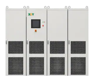
The XGY MVGS sits at the megawatt-class, medium-voltage end of this landscape: a configurable platform with direct 5 kV to 35 kV output, standard capacity from 1 MVA to 10 MVA and project expansion to 20 MVA and above. Its front-end-isolation, cascaded-power-cell architecture avoids an external output step-up transformer; four-quadrant operation can return absorbed energy to the facility grid, and the platform can be configured for ride-through, harmonic, unbalance and RoCoF workflows. Final voltage, current, event, protection, cooling and acceptance capability remains configuration-specific and is reviewed against the DUT and facility.
FAQ
Frequently asked questions
Do I need a medium-voltage grid simulator or a low-voltage one?
Match the simulator to the real connection level of your device under test. Equipment that connects at 400-480 V is served by low-voltage simulators. Devices that connect at medium voltage — MV PCS, solid-state transformers, MV UPS — have failure mechanisms such as insulation stress and protection coordination that only appear at real medium voltage, so the boundary itself must be medium voltage.
Can a grid simulator absorb power from my device under test?
Four-quadrant units can. They operate as a programmable source and as a regenerative sink, and in regenerative designs the absorbed energy is returned to the facility mains instead of being dissipated as heat — which matters greatly for megawatt-scale endurance testing.
What standards does grid-simulator testing support?
Test campaigns are typically structured around interconnection and power-quality standards such as IEEE 1547 and IEEE 1547.1, UL 1741, IEC 62116 for anti-islanding, IEEE 519 for harmonics and, in Australia, AS/NZS 4777.2. The standards define test procedures; a grid simulator is the instrument used to execute them. Supporting a standard-oriented test is not the same as the equipment holding a certification, so always confirm the compliance evidence your project needs.
What is RoCoF and why does it matter?
RoCoF is the rate of change of frequency, expressed in hertz per second. Grids with high renewable penetration can experience faster frequency movement during disturbances, and applicable grid requirements may define frequency-ramp tests. Testing this requires a source that can execute a specified frequency trajectory; the current MVGS selection guide lists programmable RoCoF above 5 Hz per second, subject to final configuration and test-plan review.
How big do grid simulators get?
The category spans bench-top kilowatt units through installation-scale megawatt systems. At the top end, the current XGY MVGS selection guide lists 1 MVA to 10 MVA standard capacity with project expansion to 20 MVA and above, and configurable direct output from 5 kV to 35 kV. The usable envelope still depends on voltage, current, duty, cooling and project configuration.
Keep exploring
Related technical resources
Related articles
Application Test Guides
How to Test a Medium-Voltage SST at Full Power
The complete SST test bench, block by block: programmable MV grid interface, regenerative DC load or battery emulator, measurement and safety layer — plus the test matrix and an RFQ checklist.
Read article
Technical Article
What Is a Solid-State Transformer (SST)? Architecture, Limits, and MVGS Testing
An engineering guide to solid-state transformer architecture, limits, and the role of a medium-voltage grid simulator in full-power SST validation.
Read article
Technical Article
Regenerative AC/DC Source Planning for EV and Power Electronics Test
A planning guide for regenerative AC/DC sources used in EV chargers, inverters, grid simulation, and power electronics validation.
Read article