

Lightwave Component Analyzers
XLA-100 Series Lightwave Component Analyzer
Modulation frequency range 10 MHz to 26.5 GHz up to 67 GHz by model; 1 Hz frequency resolution
XGY XLA-100 Series is a lightwave component analyzer that measures the bandwidth, amplitude-frequency response, phase-frequency response and group delay of electro-optical, opto-electrical and optical-optical devices. Its four models cover a modulation frequency range of 10 MHz to 26.5 GHz up to 67 GHz by model.
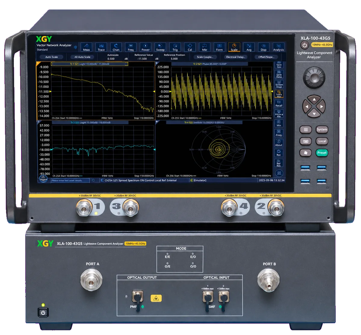
- Modulation Frequency
- 10 MHz to 26.5 GHz / 10 MHz to 43.5 GHz / 10 MHz to 50 GHz / 10 MHz to 67 GHz By model: -26G5 / -43G5 / -50G / -67G
- Working Wavelength
- 1310 ± 20 nm; 1550 ± 20 nm Internal sources
- Measurement Modes
- Electro-electro, electro-optical, optical-electro and optical-optical
- Rel. Response Accuracy
- ±0.7 dB / ±1.6 dB / ±1.6 dB / ±2.2 dB Relative; by model -26G5 / -43G5 / -50G / -67G
XLA-100 Series overview
The XLA-100 Series lightwave component analyzer characterizes the high-speed devices of an optical transmission link: modulators, lasers, PIN/APD photodetectors and fiber filters. One instrument measures their bandwidth, amplitude-frequency response, phase-frequency response and group delay, for R&D and production-line testing.
Four models, from the XLA-100-26G5 to the XLA-100-67G, cover a modulation frequency range of 10 MHz to 26.5 GHz up to 67 GHz by model. A one-click broadband sweep returns the full response, and the frequency interval and IF bandwidth are adjustable for each measurement. Besides the internal 1310 nm and 1550 nm sources, an external optical source can be connected for CWDM and DWDM component testing.
The XLA-100 connects the device under test through its optical and RF paths, so electrical, electro-optical, opto-electrical and optical-optical measurements run from the same setup. Each measurement starts with electrical calibration and optical-path parameter calibration, and probe error from chip test fixtures can be removed with de-embedding data.
Key figures
- Frequency resolution
- 1 Hz
- Frequency accuracy
- ±1 × 10⁻⁷
- External optical sources
- 1260 nm to 1630 nm
- Stated for the series
XLA-100 Series capabilities and applications
The XLA-100 Series switches between its measurement modes from one integrated interface, which covers S-parameter, impedance and time-domain measurements of common devices.
For photodetectors, the XLA-100 runs frequency response tests with rapid 3 dB bandwidth analysis. Phase-frequency response measurement gives the phase and group delay of the optoelectronic device.
The optical toolbox includes a large dynamic range optical power meter that monitors the input optical power in real time. Through the advanced settings, the light-emitting module can be set to CW output. In CW mode the polarization-maintaining laser source output has an extinction ratio greater than 20 dB and supplies an M-Z type modulator.
XLA-100 Series applications
-
Electro-optical modulators and directly modulated lasers
S11 and S21 measurements give the reflection and transmission characteristics of the device at each frequency point.
-
PIN and APD photodetectors
-
Balanced optical transmitters and receivers
-
CWDM and DWDM core components
External optical sources from 1260 nm to 1630 nm extend testing beyond the internal 1310 nm and 1550 nm bands.
-
Fiber filters and other optical-optical devices
-
On-chip optoelectronic device testing with probes
XLA-100 Series specifications
Full specification table — 14 published parameters
| Parameter | Specification |
|---|---|
| Technical specifications | |
| Modulation frequency range | 10 MHz to 26.5 GHz; 10 MHz to 43.5 GHz; 10 MHz to 50 GHz; 10 MHz to 67 GHz By model |
| Frequency accuracy | ±1 × 10⁻⁷ |
| Frequency resolution | 1 Hz |
| Working wavelength | 1310 ± 20 nm; 1550 ± 20 nm |
| Average output optical power accuracy | ±0.5 dB |
| Average input optical power measurement range | -35 dBm to +5 dBm (optical input 1); -25 dBm to +15 dBm (optical input 2) |
| Average input optical power measurement accuracy | ±0.5 dB |
| Dimensions (W × H × D) | 421 mm × 400 mm × 600 mm, excluding feet, hands |
| Power consumption | 600 W Maximum |
| Maximum safe average input power | |
| Input 1 | +7 dBm |
| Input 2 | +17 dBm |
| Measurement modes | Electro-electro, electro-optical, optical-electro and optical-optical Stated for the series |
| External optical sources | 1260 nm to 1630 nm Stated for the series |
| Extinction ratio | > 20 dB Stated for the series; CW polarization-maintaining laser source output |
The XLA-100 accuracy figures depend on the model: relative frequency response accuracy runs from ±0.7 dB on the XLA-100-26G5 to ±2.2 dB on the XLA-100-67G, and the XLA-100-26G5 also has the smallest frequency response repeatability, ±0.3 dB.
A dash in the minimum measurable frequency response row means that no value is specified for the XLA-100-26G5 and XLA-100-43G5. It does not indicate zero.
For the XLA-100-26G5 the datasheet prints the average output optical power range as -2 dBm to +4 dBm without a wavelength split; the other three models list -2 dBm to +4 dBm at 1310 nm and -2 dBm to +5 dBm at 1550 nm.
Detailed specification tables (2)
| Parameter | XLA-100-26G5 | XLA-100-43G5 | XLA-100-50G | XLA-100-67G |
|---|---|---|---|---|
| Modulation frequency range | 10 MHz to 26.5 GHz | 10 MHz to 43.5 GHz | 10 MHz to 50 GHz | 10 MHz to 67 GHz |
| Average output optical power range | -2 dBm to +4 dBm | -2 dBm to +4 dBm (1310 nm); -2 dBm to +5 dBm (1550 nm) | -2 dBm to +4 dBm (1310 nm); -2 dBm to +5 dBm (1550 nm) | -2 dBm to +4 dBm (1310 nm); -2 dBm to +5 dBm (1550 nm) |
Models: XLA-100-26G5, XLA-100-43G5, XLA-100-50G, XLA-100-67G
| Parameter | XLA-100-26G5 | XLA-100-43G5 | XLA-100-50G | XLA-100-67G |
|---|---|---|---|---|
| Minimum measurable frequency response | - | - | -60 dB | -55 dB |
| Relative frequency response accuracy | ±0.7 dB | ±1.6 dB | ±1.6 dB | ±2.2 dB |
| Absolute frequency response accuracy | ±1.8 dB | ±2.0 dB | ±2.5 dB | ±2.7 dB |
| Frequency response repeatability | ±0.3 dB | ±1.0 dB | ±1.7 dB | ±1.7 dB |
| Group delay measurement accuracy | ±13 ps | ±18 ps | ±18 ps | ±31 ps |
| Phase measurement accuracy | ±3.5° | ±4.2° | ±4.2° | ±6.0° |
| Maximum weight | 56 kg | 60 kg | 60 kg | 63 kg |
Models: XLA-100-26G5, XLA-100-43G5, XLA-100-50G, XLA-100-67G
Product and technical media
Large dynamic range, low measurement-path noise
Phase-frequency response and group delay
Optoelectronic device frequency response
User-defined data and fixture de-embedding
Single-ended and balanced photoelectric devices
More figures (1)
Electro-optical device characterization
XLA-100 Series models, configuration and compatibility
| Model | Modulation frequency range | Relative frequency response accuracy | Group delay measurement accuracy | Maximum weight |
|---|---|---|---|---|
| XLA-100-26G5 | 10 MHz to 26.5 GHz | ±0.7 dB | ±13 ps | 56 kg |
| XLA-100-43G5 | 10 MHz to 43.5 GHz | ±1.6 dB | ±18 ps | 60 kg |
| XLA-100-50G | 10 MHz to 50 GHz | ±1.6 dB | ±18 ps | 60 kg |
| XLA-100-67G | 10 MHz to 67 GHz | ±2.2 dB | ±31 ps | 63 kg |
The XLA-100 model choice follows the highest modulation frequency of your devices. Lower-frequency models have tighter accuracy: group delay accuracy is ±13 ps on the XLA-100-26G5 against ±31 ps on the XLA-100-67G, and the XLA-100-26G5 is also the lightest at 56 kg.
XLA-100 Series selection guidance
- Format
- Lightwave component analyzer; four models by modulation frequency range
- Coverage
- Modulation frequency range 10 MHz to 26.5 GHz, 43.5 GHz, 50 GHz or 67 GHz by model; 1 Hz frequency resolution
- Best for
- Bandwidth, frequency response, phase and group-delay characterisation of modulators, lasers, photodetectors and optical transceiver components.
XLA-100 Series technical resources
Request a quote for the XLA-100 Series
Share the application, required configuration and documentation needs for the XLA-100 Series, or compare it with other products in the Lightwave Component Analyzers category first. XGY Tek reviews each request and confirms model, options and delivery documentation in the quotation.
Before requesting a quote
For an XLA-100 Series request, describe the devices you will measure and how they connect.
- The highest modulation frequency your devices need, which selects the XLA-100-26G5, XLA-100-43G5, XLA-100-50G or XLA-100-67G.
- The device types and measurement modes: E/O, O/E, O/O or electrical, single-ended or balanced.
- Whether devices are measured on-chip with probes, and whether fixture de-embedding data is available.
- The cables, adapters and delivery items you expect, because the datasheet does not list a standard configuration or accessories.
XLA-100 Series related products and FAQ
-
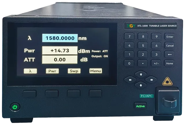
XTL-1600 Tunable Laser Source
High-precision tunable laser source with wavelength tuning range 1500 to 1600 nm
View details -
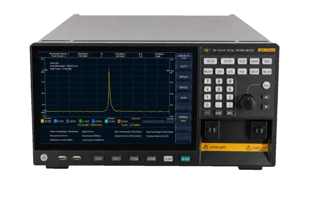
XOA-1700-R20 / XOA-1700-R10 Optical Spectrum Analyzers
600 to 1700 nm optical spectrum analysis with 20 pm or 10 pm minimum selectable wavelength resolution
View details -
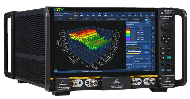
YNA-720 Series Vector Network Analyzer
Frequency range 10 MHz to 26.5 GHz / 10 MHz to 44 GHz / 10 MHz to 67 GHz by model
View details