
RF Accessories
GPM40-U USB CW Power Sensor
50 MHz–40 GHz USB CW Power Sensor
GPM40-U connects CW power measurements to a host computer through USB-TMC, with a 2.4 mm male RF port and frequency coverage to 40 GHz.
Get a Quote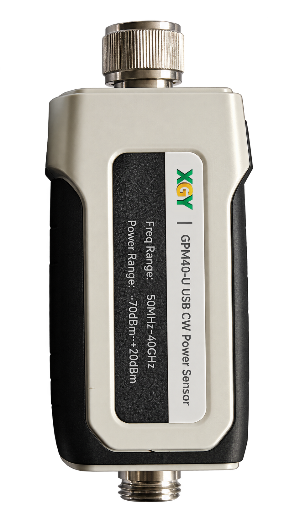
- Frequency range
- 50 MHz to 40 GHz
- Power Measurement
- RF connector
- 2.4 mm male
- Control interface
- USB 2.0 interface, compatible with USB-TMC
- Weight
- <0.4 kg
Overview
GPM40-U measures CW power from 50 MHz to 40 GHz for field testing, production and system integration. USB 2.0 with USB-TMC compatibility provides control, while supplied software displays readings on a host computer.
The −70 to +20 dBm measurement range includes special preparation below −40 dBm. The ±0.25 dB amplitude accuracy applies from −40 to +20 dBm with DUT SWR below 1.20 and an average count of 128.
Additional product details
GPM40-U is a USB CW power sensor for field testing, production line testing and system integration. Its USB interface connects power measurement to a host computer display.
Key Capabilities & Applications
Measure CW power to 40 GHz
The 2.4 mm male sensor covers 50 MHz to 40 GHz and −70 to +20 dBm. Maximum input-power damage limits are separate from the measurement range.
Prepare low-power measurements
Below −40 dBm, connect to the DUT and preheat for one hour in a temperature-controlled environment. Switch Step Detection off, select averaging and perform external zero calibration, then enable the DUT output and wait one minute.
Connect readings to the host
USB 2.0 control is compatible with USB-TMC. The supplied software supports Windows host display, and measurement reading rate depends on aperture time rather than the ADC sampling rate.
Common applications
- Field testing
- Production line testing
- System integration
Technical Specifications
| Parameter | Specification |
|---|---|
| Power Measurement | |
| Frequency range | 50 MHz to 40 GHzPower Measurement |
| Measurement power range | -70 dBm to +20 dBmBelow -40 dBm; one hour preheat; external zero calibration |
| Amplitude measurement accuracy | ±0.25 dB-40 dBm to +20 dBm, DUT SWR <1.20, average count 128 |
| Maximum input power, average | +23 dBmPower Measurement; Absolute maximum; Average input power; damage limit |
| Maximum input power, peak | +26 dBmPower Measurement; Absolute maximum; Duration <10 µs; damage limit |
| Maximum measurement speed | 50,000 readings/sMeasurement rate equals 1/aperture time |
| Interface and General Specifications | |
| RF connector | 2.4 mm male |
| Control interface | USB 2.0 interface, compatible with USB-TMC |
View all 19 specifications
| Parameter | Specification |
|---|---|
| Power Measurement | |
| Zero setting | ±70 pWPower Measurement; One hour preheat in a temperature-controlled environment; external zero calibration |
| Measurement noise | ±80 pWOne hour preheat in a temperature-controlled environment; external zero calibration |
| Maximum ADC sampling rate | 1 MSamples/sPower Measurement; ADC design specification |
| Interface and General Specifications | |
| Dimensions (W × H × D) | 51.5 × 33.5 × 124.5 mm |
| Weight | <0.4 kg |
| Operating temperature | -10°C to 50°C |
| Storage temperature | -40°C to 70°C |
| Recommended calibration cycle | 12 months |
| Power requirement | +5 V, 500 mA |
| Display | Host computer display |
| User interface language | Chinese / English |
Detailed performance and interface tables (3)
| Specification | Value |
|---|---|
| 50 MHz ≤ f ≤ 2 GHz | 1.15 |
| 2 GHz < f ≤ 12.4 GHz | 1.20 |
| 12.4 GHz < f ≤ 18 GHz | 1.26 |
| 18 GHz < f ≤ 26.5 GHz | 1.35 |
| 26.5 GHz < f ≤ 40 GHz | 1.50 |
| Specification | Value |
|---|---|
| 50 MHz ≤ f ≤ 18 GHz | 0.19 dB |
| 18 GHz < f ≤ 26.5 GHz | 0.21 dB |
| 26.5 GHz < f ≤ 40 GHz | 0.23 dB |
| Specification | Value |
|---|---|
| Operating system | Windows 11 (64-bit); Windows 10 and Windows 7 (32-bit and 64-bit) |
| Processor | 1 GHz or higher; recommended 2 GHz or higher |
| Memory | 2 GB or higher; recommended 4 GB or higher |
| Disk space | 1.0 GB or higher |
| Display resolution | 1280 × 1024 or higher |
Performance notes
The maximum input powers are damage limits, not the measurement range. Exceeding either limit may damage or burn out the sensor.
Low-power measurement. Below -40 dBm, connect the sensor to the DUT and preheat for one hour in a temperature-controlled environment. Set Step Detection to Off, configure an appropriate number of averages and perform External Zero Calibration. Then enable the DUT signal output, wait one minute and observe the results. The results include zero-setting and measurement-noise errors.
Maximum input power. Maximum input power is the highest power the sensor can handle. Exceeding the stated limit may damage or burn out the sensor.
Accuracy conditions. The ±0.25 dB accuracy applies from -40 dBm to +20 dBm with DUT SWR <1.20 and an average count of 128. Below -40 dBm, zero-setting and measurement-noise effects on measurement accuracy increase as the measured power decreases.
Calibration and measurement uncertainty. Calibration uncertainty includes inherent linear deviation, temperature effects and expanded uncertainty arising from sensor calibration. User measurement uncertainty includes this calibration uncertainty plus sensor-to-DUT port mismatch, zero-setting uncertainty and measurement noise.
Zero setting. Zero setting is the sensor’s fixed output deviation when no signal is applied. Non-ideal internal circuits, including amplifier offset and thermoelectric potential, or external interference cause this deviation, which significantly affects low-power measurements. Preheat for one hour in a temperature-controlled environment and perform external zero calibration before testing.
Measurement noise. Measurement noise is the effect of internal circuit noise on the measurement and is more pronounced for small signals. Measurement-noise testing requires one hour of preheating in a temperature-controlled environment followed by external zero calibration.
ADC sampling rate. Maximum sampling rate is the highest conversion rate of the ADC and is a design specification of the sensor.
Measurement reading rate. Maximum measurement rate is the maximum amount of sensor data that can be read per second. It is correlated with aperture time: measurement rate equals 1/aperture time. The reading rate is governed by aperture time and is distinct from the ADC sampling rate.
Measurement uncertainty also includes sensor-to-DUT mismatch, zero-setting uncertainty and measurement noise.
Specifications are subject to change without notice.
Models, Configuration & Compatibility
GPM40-U
Standard delivery contents
- USB cable (×1) — 2.0 m
- Software and documentation CD (×1) — Manuals and power measurement display software
- Certificate of conformity (×1)
Control interfaces and software
The USB 2.0 control interface is compatible with USB-TMC and uses a host computer display. The supplied software and documentation CD includes manuals and power measurement display software. Supported systems are Windows 11 (64-bit), Windows 10 and Windows 7 (32-bit and 64-bit).
USB 2.0 · USB-TMC · Host PC display
Technical Resources
Selection guidance
Format: USB CW power sensor
Coverage: Power measurement frequency range 50 MHz to 40 GHz; USB 2.0 control; 2.4 mm male RF connector
Best for: Continuous wave power measurement in field testing, production line testing and system integration.
Compare products in the RF Accessories categorySend the operating envelope, configuration and acceptance evidence you need; the quotation confirms model, options and delivery documentation.
Related Products & FAQ
RF Accessories
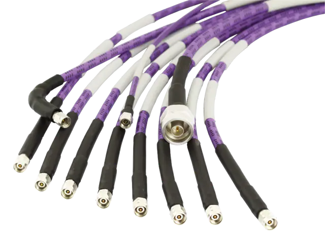
PT Series
Precision Test Cable
Frequency range: DC to 110 GHz (By configuration)
View detailsRF Accessories
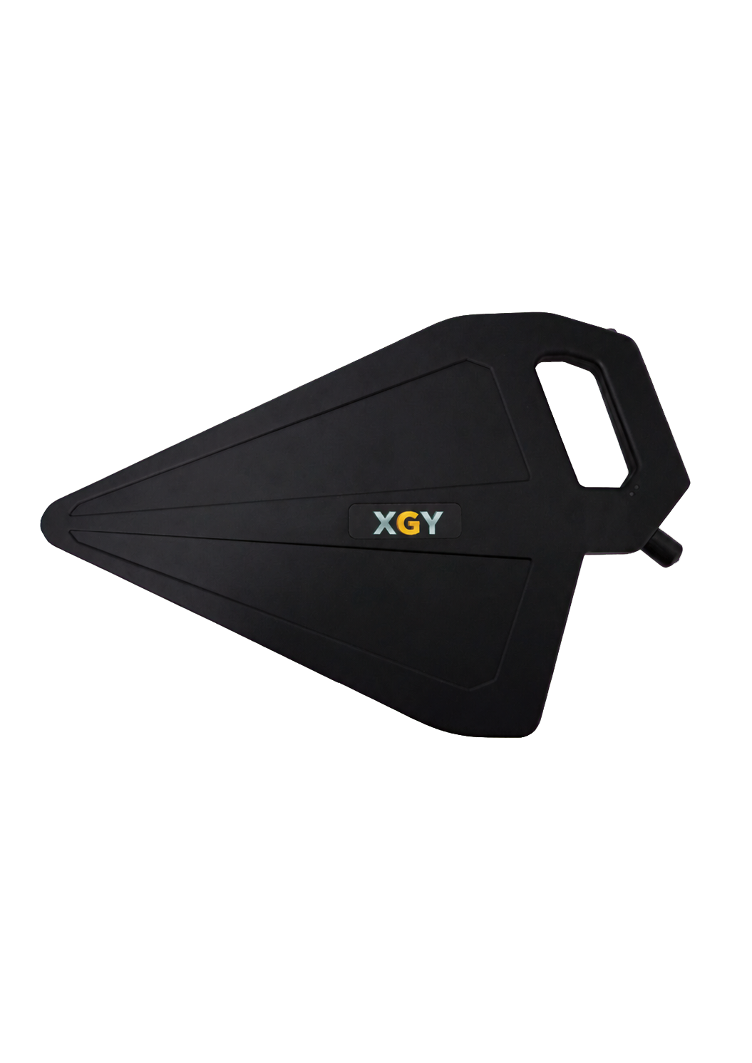
XDA-1000 / XDA-2000
Active Directional Antennas
Frequency Range: XDA-1000: 500 MHz to 10 GHz; XDA-2000: 500 MHz to 20 GHz
View detailsRF Accessories
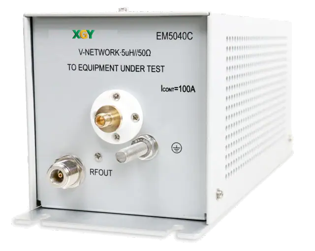
EM5040 Series
LISN
Frequency Range: 9 kHz to 30 MHz (E/A/B); 100 kHz to 200 MHz (C)
View details