
RF Accessories
EM5040 Series LISN
V-Type LISNs for Conducted Emissions Testing
Choose standard, limiter-equipped, CM/DM or high-current LISN configurations for conducted disturbance measurements and EMC debugging.
Get a Quote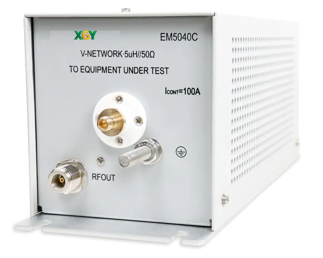
- Channels
- Single-phase L/N
- Power
- 16 A / 100 A models
- Key Spec
- 9 kHz to 200 MHz
- Type
- V-type LISN
Overview
EM5040 LISNs provide a defined impedance for the equipment under test and couple conducted disturbance signals to a receiver or spectrum analyzer. EM5040E, A and B cover 9 kHz to 30 MHz at 16 A; EM5040C covers 100 kHz to 200 MHz at 100 A rated current.
Choose the model around the test circuit and workflow: E provides the standard single-phase function, A adds receiver protection, B provides CM/DM separation, and C serves high-current single-line measurements.
Additional product details
Stable Impedance for Accurate Conducted Emission Measurement
The EM5040 Series is a family of V-type line impedance stabilization networks designed for conducted emission testing and EMC debugging. These LISNs provide a stable impedance environment for the equipment under test while coupling disturbance signals to external receivers or analyzers for accurate measurement.
The series includes multiple configurations for different workflows. EM5040E provides the standard single-phase LISN function, EM5040A adds a built-in 10 dB limiter and optional 150 kHz high-pass filter, EM5040B adds common-mode and differential-mode separation for advanced debugging, and EM5040C targets high-current, higher-frequency single-line testing for industrial and automotive-related applications.
Model Selection Guide
| Model | Positioning | Key Function | Best Fit |
|---|---|---|---|
| EM5040E | Standard single-phase LISN | Basic V-type LISN for conducted disturbance voltage measurement | General CE testing and baseline EMC measurement |
| EM5040A | Protected test setup LISN | Built-in 10 dB limiter and optional 150 kHz high-pass filter | Receiver protection and compliance-oriented workflows |
| EM5040B | Advanced EMI debugging LISN | CM/DM separator for common-mode and differential-mode analysis | EMI filter debugging and interference root-cause analysis |
| EM5040C | High-current / high-frequency LISN | 100 kHz to 200 MHz range and 100 A rating | Industrial, automotive, and high-current EMC test scenarios |
EM5040E - Standard LISN
| Parameter | Value |
|---|---|
| Frequency Range | 9 kHz to 30 MHz |
| Circuit Type | (50uH + 5 ohm) |
| Measurement Circuit | Single phase two wire L/N |
| AC Voltage | 0 to 264 VAC, 50/60 Hz +/-5% |
| DC Voltage | 0 to 375 VDC |
| Current Rating | 16 A |
| Output Connector | 50 ohm BNC female |
| Artificial Hand | Yes |
| Weight | 5 kg |
EM5040A - Protected LISN
| Parameter | Value |
|---|---|
| Frequency Range | 9 kHz to 30 MHz |
| Circuit Type | (50uH + 5 ohm) |
| Measurement Circuit | Single phase two wire L/N |
| AC Voltage | 0 to 264 VAC, 50/60 Hz +/-5% |
| DC Voltage | 0 to 375 VDC |
| Current Rating | 16 A |
| Output Connector | 50 ohm BNC female |
| Limiter | 10 dB, 130 dBuV threshold |
| High-Pass Filter | Optional 9 kHz / 150 kHz |
| Weight | 5.25 kg |
EM5040B - CM/DM LISN
| Parameter | Value |
|---|---|
| Frequency Range | 9 kHz to 30 MHz |
| Circuit Type | (50uH + 5 ohm) |
| Measurement Circuit | Single phase two wire L/N |
| AC Voltage | 0 to 264 VAC, 50/60 Hz +/-5% |
| DC Voltage | 0 to 375 VDC |
| Current Rating | 16 A |
| Output Connector | 50 ohm BNC female |
| CM/DM Separator | Yes |
| Weight | 5.25 kg |
EM5040C - High-Current LISN
| Parameter | Value |
|---|---|
| Frequency Range | 100 kHz to 200 MHz |
| Circuit Type | (5uH + 1 ohm) |
| Measurement Circuit | Single wire |
| AC Voltage | 0 to 250 VAC, 0 to 400 Hz |
| DC Voltage | 0 to 600 V |
| Current Rating | 100 A rated / 500 A short-time |
| Output Connector | 50 ohm N female |
| Weight | 1.8 kg |
Key Capabilities & Applications
Establish the impedance network
E/A/B use a (50 µH + 5 ohm) || 50 ohm V-network for single-phase L/N measurements. C uses a (5 µH + 1 ohm) || 50 ohm network for single-wire testing.
Select protection or EMI debugging
EM5040A includes a 10 dB limiter and offers an optional 150 kHz high-pass filter. EM5040B adds common-mode and differential-mode separation. EM5040E requires an external limiter for receiver protection.
Handle the higher-current circuit
EM5040C is rated for 100 A continuous current and 500 A for less than 30 seconds. It covers 100 kHz to 200 MHz and has an N female output; E/A/B use BNC female outputs.
All capabilities and operating conditions
Standards-Oriented
Designed to meet CISPR16-1-2:2006 requirements for V-network conducted emission testing
Stable Reference
Provides consistent impedance for the DUT while isolating unwanted mains interference
EMI Debug Ready
Selected models support common-mode and differential-mode analysis for filter debugging
Receiver Protection
Limiter-equipped model helps protect sensitive receivers and spectrum analyzers
Series Flexibility
Covers standard single-phase, protected, CM/DM, and high-current high-frequency use cases
Common applications
- R&D conducted disturbance voltage measurement - single-phase electronic and electrical equipment testing
- EMI filter debugging - CM/DM interference analysis in switching power supplies
- Industrial and automotive compliance testing - VDE, CISPR25, MIL-STD, and ISO7637 workflows on EM5040C
- Production quality assurance - standardized EMC testing for consistent conducted-emission performance
Technical Specifications
| Parameter | Specification |
|---|---|
| Product Family | EM5040E / EM5040A / EM5040B / EM5040C |
| Frequency Range | 9 kHz to 30 MHz (E/A/B); 100 kHz to 200 MHz (C) |
| Circuit Type | (50uH + 5 ohm) || 50 ohm V-type (E/A/B); (5uH + 1 ohm) || 50 ohm (C) |
| AC Voltage | 0 to 264 VAC (E/A/B); 0 to 250 VAC (C) |
| Current Rating | 16 A (E/A/B); 100 A rated, 500 A short-time (C) |
| Standards | CISPR 16-1-2:2006 |
| Artificial Hand | 510 Ω + 220 pF; E/A/B have artificial-hand function, C does not |
| EM5040E Receiver Protection | External limiter should be added to protect the test receiver |
View all 17 specifications
| Parameter | Specification |
|---|---|
| EM5040C Short-Time Current | 500 A for less than 30 s; 100 A rated continuous current |
| Ground Protection, E/A/B | Side metal panel grounding; rear panel 4 mm butterfly bolt grounding |
| Ground Protection, C | Two M8 bolts; bottom metal panel connected to ground plane with screws |
| Operating Temperature | 0 to 45 °C |
| Storage Temperature | -20 to 70 °C |
| Safety Standard | EN61010-1 |
| Dimensions, E/A/B | 338 × 237 × 133 mm (L × W × H) |
| Dimensions, C | 322 × 122 × 128 mm (L × W × H) |
| Supplied Accessories | LISN; BNC male RF cable, 2 m; BNC female to N male adapter; instruction manual; warranty card; test report |
Specifications are subject to change without notice.
Models, Configuration & Compatibility
EM5040
EM5040E — Standard
9 kHz to 30 MHz, 16 A, single-phase L/N network. Add an external limiter to protect the receiver.
EM5040A — Protected
9 kHz to 30 MHz, 16 A, built-in 10 dB limiter and optional 150 kHz high-pass filter.
EM5040B — CM/DM
9 kHz to 30 MHz, 16 A, with common-mode and differential-mode separation for EMI debugging.
EM5040C — High Current
100 kHz to 200 MHz, single-wire network, 100 A rated continuous and 500 A for less than 30 seconds.
Control interfaces and software
The EM5040 Series LISN should be scoped with the DUT power path, receiver or spectrum analyzer, limiter needs, grounding plan and acceptance evidence for conducted-emissions work.
CISPR 16-1-2 workflow · Conducted-emissions setup · Receiver protection · CM / DM analysis · High-current option
Technical Resources
Selection guidance
Format: V-type LISN
Coverage: 9 kHz to 30 MHz or 100 kHz to 200 MHz; 16 A or 100 A rated by model
Best for: Conducted disturbance-voltage measurement, EMC debugging, compliance validation, and CM/DM analysis.
Compare products in the RF Accessories categoryConfirm LISN frequency range, current rating, circuit type, receiver-protection needs and conducted-emissions workflow before selecting the EM5040 Series LISN.
Looking for EMC test equipment or a custom LISN solution?
XGY Tek specializes in power-line stabilization and EMC validation setups for conducted emission measurement, EMI debugging, and compliance testing.
Related Products & FAQ
RF Accessories
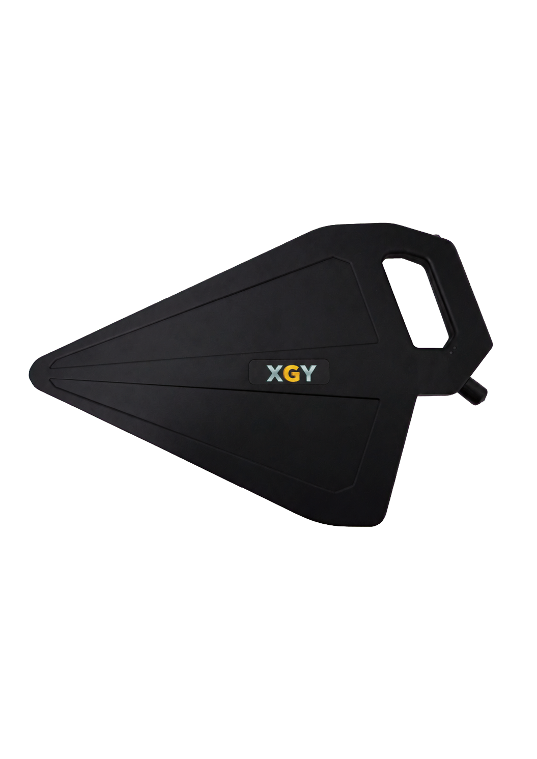
XDA-1000 / XDA-2000
Active Directional Antennas
Frequency Range: XDA-1000: 500 MHz to 10 GHz; XDA-2000: 500 MHz to 20 GHz
View detailsRF Accessories
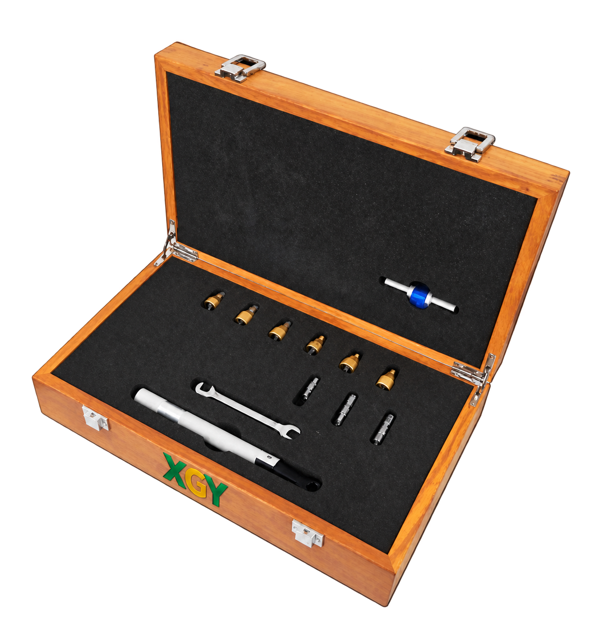
MCAL-KIT-CY 40
Mechanical Calibration Kit
Frequency range: DC–40 GHz (23 ± 3 °C; DC to 10 MHz referenced to 10 MHz, not separately tested)
View detailsRF Accessories
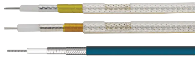
GL Series
Phase-Stable Test Cable
Frequency range: DC to 26.5 GHz (By configuration)
View details