
THz Modules
High Precision Passive Waveguide Components
Passive Waveguide Components for mmWave and THz Chains
The passive waveguide portfolio includes fixed attenuators, couplers, filters, Faraday isolators and waveguide-to-coaxial adapters. Selected component families reach 500 GHz; each function has its own band and waveguide range.
Get a Quote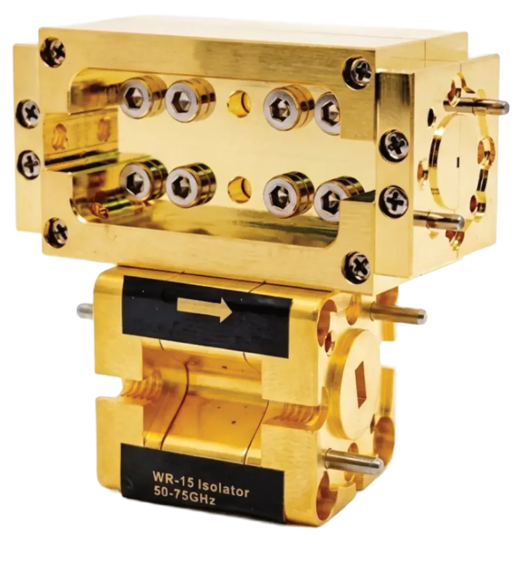
- Frequency
- Up to 500 GHz
- Waveguide
- WR-22 to WR-2.2
- Power handling
- Up to 10 W in lower bands
- Stated for the series
- Waveguide filters
- 26.5 to 330 GHz, BPF / LPF / HPF / BSF
Overview
The passive waveguide portfolio includes fixed attenuators, couplers, filters, Faraday isolators and waveguide-to-coaxial adapters. Selected component families reach 500 GHz; each function has its own band and waveguide range.
Additional product details
The High Precision Passive Waveguide Components lineup includes fixed attenuators and directional couplers up to 500 GHz, plus waveguide filters, diplexers, Faraday isolators, straight sections, bends, and waveguide-to-coaxial adapters.
Along with waveguide-to-coaxial adapters supporting connectors down to 0.6mm, our components empower rapid and reliable integration.
Waveguide size is the first constraint on any of these choices, not frequency: a WR-2.2 attenuator and a WR-19 attenuator cannot be swapped, so the band plan for the chain has to be fixed before the component list is. Where a chain crosses bands, the waveguide-to-coaxial adapters are the transition point worth specifying early.
Key Capabilities & Applications
Attenuation and coupling
Fixed attenuators and directional couplers cover 40–500 GHz. Standard attenuation values are 3 / 6 / 10 / 20 / 30 / 40 dB, with model-dependent power handling up to 10 W in lower bands.
Filtering and isolation
Filters cover 26.5–330 GHz with band-pass, low-pass, high-pass or band-stop forms. Faraday isolators cover 50–220 GHz; insertion loss is as low as 1.0 dB on applicable models.
Mechanical signal-chain routing
Waveguide-to-coaxial adapters, straight sections, tapers, twists and bends support interconnection. Select waveguide size, flange and connector for the intended band.
All capabilities and operating conditions
High-power attenuation
Fixed attenuator modules list standard 3, 6, 10, 20, 30, and 40 dB values with model-dependent power handling up to 10 W.
Coupling and filtering options
Directional couplers, dual-directional couplers, waveguide filters, and diplexers support measurement and routing functions.
Source protection
Compact Faraday isolators cover 50 to 220 GHz for source protection and signal isolation.
Common applications
- Signal-level control
- Measurement pickoff and monitoring
- Waveguide frequency shaping
- Source protection and transitions
Applications and test requirements
Signal-level control
Fixed attenuation values for mmWave and THz waveguide chains.
Measurement pickoff and monitoring
Waveguide frequency shaping
Source protection and transitions
Technical Specifications
| Parameter | Specification |
|---|---|
| Frequency | Up to 500 GHz |
| Waveguide | WR-22 to WR-2.2 |
| Power handling | Up to 10 W in lower bandsStated for the series |
| Fixed attenuators | 40 to 500 GHz, WR-19 to WR-2.2 |
| Waveguide filters | 26.5 to 330 GHz, BPF / LPF / HPF / BSF |
| Faraday isolators | 50 to 220 GHz, WR-15 to WR-05 |
| Directional couplers | 40 to 500 GHz, WR-19 to WR-2.2, 3 to 40 dB coupling, single-port monitoring |
| Waveguide-to-coaxial adapters | Up to D band, WR-28 to WR-06, connectors down to 0.6 mm, low VSWR |
View all 13 specifications
| Parameter | Specification |
|---|---|
| Dual-directional couplers | 50 to 330 GHz, WR-15 to WR-03, 10 / 16 / 20 / 26 / 30 dB coupling, dual-port monitoring |
| Attenuation values | 3 / 6 / 10 / 20 / 30 / 40 dB standard, up to 10 W |
| Isolator insertion loss | As low as 1.0 dB |
| Filter bands | Ka to J bands, custom center frequency and bandwidth |
| Waveguide routing sections | RSW / SSW straight sections; WT taper; TW twist; HB / EB bends |
Specifications are subject to change without notice.
Models, Configuration & Compatibility
No model codes are listed for the High Precision Passive Waveguide Components; part numbers are confirmed in the quotation.
Model comparison (5)
Fixed attenuator part selection (11 rows)
| Part number | Band | Frequency (GHz) | Attenuation (dB) | Power (W) | Waveguide |
|---|---|---|---|---|---|
| FATXX-19HPV | U | 40–60 | 3/6/10/20/30/40 | 10 | WR-19 |
| FATXX-15HPV | V | 50–75 | 3/6/10/20/30/40 | 10 | WR-15 |
| FATXX-12HPV | E | 60–90 | 3/6/10/20/30/40 | 10 | WR-12 |
| FATXX-10HPV | W | 75–110 | 3/6/10/20/30/40 | 10 | WR-10 |
| FATXX-08HPV | F | 90–140 | 3/6/10/20/30/40 | 5 | WR-08 |
| FATXX-06HPV | D | 90–140 | 3/6/10/20/30/40 | 2 | WR-06 |
| FATXX-05HPV | G | 140–220 | 3/6/10/20/30 | 1 | WR-05 |
| FATXX-04HPV | H | 170–260 | 3/6/10/20/30 | 0.5 | WR-04 |
| FATXX-03HPV | J | 220–330 | 6/10/20/30 | 0.2 | WR-03 |
| FATXX-2.8HPV | - | 260–400 | 10/20 | 0.1 | WR-2.8 |
| FATXX-2.2HPV | - | 330–500 | 10/20 | 0.1 | WR-2.2 |
Frequency, values and power are shown for each part. The D-band WR-06 entries show 90–140 GHz; confirm the frequency range before ordering.
Directional coupler part selection (11 rows)
| Part number | Band | Frequency (GHz) | Coupling (dB) | Power (W) | Waveguide |
|---|---|---|---|---|---|
| CXX-19A | U | 40–60 | 3/6/10/20/30/40 | 10 | WR-19 |
| CXX-15A | V | 50–75 | 3/6/10/20/30/40 | 10 | WR-15 |
| CXX-12A | E | 60–90 | 3/6/10/20/30/40 | 10 | WR-12 |
| CXX-10A | W | 75–110 | 3/6/10/20/30/40 | 10 | WR-10 |
| CXX-08A | F | 90–140 | 3/6/10/20/30/40 | 5 | WR-08 |
| CXX-06A | D | 90–140 | 3/6/10/20/30/40 | 2 | WR-06 |
| CXX-05A | G | 140–220 | 3/6/10/20/30 | 1 | WR-05 |
| CXX-04A | H | 170–260 | 3/6/10/20/30 | 0.5 | WR-04 |
| CXX-03A | J | 220–330 | 6/10/20/30 | 0.2 | WR-03 |
| CXX-2.8V | - | 260–400 | 10/20 | 0.1 | WR-2.8 |
| CXX-2.2V | - | 330–500 | 10/20 | 0.1 | WR-2.2 |
Frequency, values and power are shown for each part. The D-band WR-06 entries show 90–140 GHz; confirm the frequency range before ordering.
Dual-directional coupler part selection (8 rows)
| Part number | Band | Frequency (GHz) | Coupling (dB) | Power (W) | Waveguide |
|---|---|---|---|---|---|
| DCXXS-15V | V | 50–75 | 10/16/20/26/30 | 10 | WR-15 |
| DCXXS-12V | E | 60–90 | 10/16/20/26/30 | 10 | WR-12 |
| DCXXS-10V | W | 75–110 | 10/16/20/26/30 | 10 | WR-10 |
| DCXXS-08V | F | 90–140 | 10/16/20/26/30 | 5 | WR-08 |
| DCXXS-06A | D | 90–140 | 10/16/20/26/30 | 2 | WR-06 |
| DCXXS-05V | G | 140–220 | 10/16/20/26/30 | 1 | WR-05 |
| DCXXS-04A | H | 170–260 | 10/16/20 | 0.5 | WR-04 |
| DCXX-03A | J | 220–330 | 10/16 | 0.2 | WR-03 |
Frequency, values and power are shown for each part. The D-band WR-06 entries show 90–140 GHz; confirm the frequency range before ordering.
Faraday isolator part selection (6 rows)
| Part number | Band | Frequency (GHz) | Insertion (dB) | Power (W) | Waveguide |
|---|---|---|---|---|---|
| ISO-15C1 | V | 50–75 | –1.0 | 1.0 | WR-15 |
| ISO-12C1 | E | 60–90 | –1.0 | 1.0 | WR-12 |
| ISO-10C1 | W | 75–110 | –1.0 | 1.0 | WR-10 |
| ISO-08C1 | F | 90–140 | –1.5 | 0.5 | WR-08 |
| ISO-06C1 | D | 110–170 | –2.0 | 0.5 | WR-06 |
| ISO-05C1 | G | 140–220 | –3.0 | 0.1 | WR-05 |
Confirm the sign convention before interpreting the insertion figures as positive loss, and confirm the guaranteed isolation for the selected part.
Waveguide-to-coaxial connector pairs (5 rows)
| Waveguide | Coaxial connectors |
|---|---|
| WR-19 | 1.85 mm |
| WR-15 | 1.85 / 1.0 mm |
| WR-12 | 1.0 / 1.35 / 1.85 mm |
| WR-10/08 | 1.0 / 0.8 mm |
| WR-06 | 0.8 / 0.6 mm |
End-launch and right-angle launches are available; custom waveguide/connector pairs are described.
Technical Resources
Selection guidance
Format: Passive waveguide portfolio
Coverage: Attenuators, couplers, filters, isolators, and waveguide-to-coaxial adapters
Best for: Routing, conditioning, coupling, filtering, isolation, and measurement-plane completion around active modules.
Compare products in the THz Modules categorySend the operating envelope, configuration and acceptance evidence you need; the quotation confirms model, options and delivery documentation.
Related Products & FAQ
THz Modules
mmWave Active Waveguide Modules
Frequency range: 33 to 500 GHz
View detailsTHz Modules
GT-W-AM6-75110
Full W-Band Active Multiplier
Frequency range: 75 to 110 GHz
View detailsTHz Modules
GT-E-DNC-7681
Bench-Top E-Band Down-Converter
RF frequency: 76 to 81 GHz (Typical)
View details