
In brief
A battery energy storage PCS — the power conversion system between battery and grid — is the network's only fully bidirectional citizen: it imports and exports real power, supplies and absorbs reactive power, and switches roles in fractions of a second to sell services. Testing one therefore means every test twice — charging and discharging — plus the transitions between. This checklist organises the programme into five domains: grid compliance, power performance, battery interface, protection and abnormal conditions, and endurance.
Key takeaways
- Bidirectionality is the organising fact: ride-through, power quality, efficiency and protection all have a charging case, a discharging case, and a mid-event transition case — and field incidents live in the third.
- Storage earns revenue on speed, so command-response testing — how fast and how accurately the PCS follows power and frequency-service commands — is a first-class campaign, not a footnote.
- The battery side is a test boundary of its own: DC operating windows, and the strategic choice between testing against real batteries and programmable battery emulation.
- Grid-side evidence needs a four-quadrant bench: only a source that can absorb full export and supply full import exercises both directions of every test.
- Cell and battery validation is a separate discipline — this checklist proves the converter and its citizenship, not the electrochemistry behind it.
The PCS: the grid’s fully bidirectional citizen
Most grid-connected equipment has a dominant direction: generators export, loads import, and their test programmes inherit that asymmetry. A storage PCS has none. Across a day it imports megawatts (charging), exports megawatts (discharging), holds at zero exchanging only reactive power, and — the commercially decisive part — transitions between these states on command, in the response times that frequency and balancing markets pay for. In the four-quadrant language of the fundamentals guide, the PCS is the one device class that genuinely lives in all four quadrants as its business model. Two testing consequences follow before any checklist is written. Symmetry: every behaviour with a direction must be verified in both — efficiency maps, current quality, ride-through response, protection behaviour — because converter operating points, control modes and thermal profiles differ between import and export, and a machine proven in one direction is half-proven. Transitions: the moments between states — a charge-to-discharge reversal commanded mid-frequency-event, a ride-through entered while importing and exited exporting — are where control complexity concentrates and where the checklist below deliberately places test items, because field misbehaviour reports cluster exactly there.
Domain 1 — Grid-side compliance, both directions
The PCS meets the full compliance apparatus of the standards guide — as a generator when exporting, as a load when importing, and as an inverter-based resource throughout. The campaign is the familiar library with the bidirectional twist applied to every family. Ride-through: LVRT, HVRT and ZVRT profiles executed while charging, while discharging, and — the discriminating cases — with commanded transitions during events, verifying the code-specified behaviour (stay connected, support voltage, resume correctly) holds regardless of the pre-event direction. Frequency and RoCoF: withstand and ramp testing across the code’s window, plus the frequency-response functions storage exists to sell — under- and over-frequency response from both initial states, since raising output and reducing charging are different control actions with the same market name. Anti-islanding: detection and disconnection per the applicable procedure, verified in both power-flow directions, and shown to coexist with the ride-through settings rather than defeat them. Power quality: harmonic emission and immunity measured charging and discharging across the power range, because modulation depth and operating point move emission spectra. Every item lands as evidence per the evidence guide — profile applied, response captured, both directions on the record.
Domain 2 — Power performance and the speed the market pays for
Storage economics rest on two performance surfaces the checklist must map. The efficiency surface: conversion losses measured across the power range in both directions — the two maps whose product bounds the converter’s contribution to round-trip efficiency — at representative DC voltages across the battery window, because efficiency at one operating point is a brochure, and the surface is the asset model’s input. The response surface: for every service the project will bid — energy shifting, frequency services, ramping products — the command-to-response behaviour: latency from command receipt to power movement, ramp rate, settling accuracy, and sustained-accuracy under continuous regulation signals. In the Australian context this is the territory of AEMO’s Market Ancillary Service Specification, which defines how frequency-service response is measured and verified — take the current specification’s terms, and treat equivalent frameworks in other markets the same way. The bench implication is worth stating plainly: response testing needs a grid interface that can both command the conditions (frequency trajectories per the RoCoF guide) and absorb or supply the resulting power swings at full scale — which is the four-quadrant requirement again, now with dynamics attached.
Domain 3 — The battery side: real cells or programmable emulation?
The PCS’s second boundary is DC, and the programme must decide what stands behind it. Testing against the real battery brings authenticity — genuine impedance, genuine voltage travel with state of charge, genuine BMS interaction — at the price of constraint: state of charge becomes a scheduling tyrant, extreme-window and fault-adjacent conditions are limited by the cells’ safety envelope, and repeatability suffers because no two states of charge are quite alike. Battery emulation — a programmable DC source-sink presenting battery-like voltage, impedance and dynamics — inverts the trade: any point in the DC window on demand, edge and fault-adjacent conditions programmable, perfect repeatability for regression, at the price of modelling fidelity and the absence of a real BMS conversation. Mature programmes use both in sequence: emulation for characterisation, envelope exploration and regression (where its programmability is decisive), the real battery for integration verification and the BMS-coordination items no emulator fully reproduces. Checklist items for the boundary itself: operation verified across the full DC voltage window including the corners; behaviour at window limits (graceful derating versus abrupt tripping, per specification); DC-side power quality (ripple current into the battery, against the battery supplier’s limits); and the BMS interface choreography — limits respected, states honoured, contactor sequencing correct.
Domains 4 and 5 — Protection, abnormal conditions, endurance
Domain 4 collects the tests everyone hopes are boring. Grid-side faults: response to short circuits and voltage collapse at the point of connection, in both power-flow directions, with fault-current contribution characterised against the code’s expectations. DC-side faults: the harder family — DC short circuits, ground faults on the battery side, insulation degradation — where protection must act at converter speed and the earthing scheme’s behaviour (per the common-mode guide’s disciplines) is part of the test definition. Communication loss: EMS link lost mid-service, BMS link lost mid-charge — each with a specified safe behaviour to verify, because “undefined” is the one unacceptable answer. And restart choreography: recovery from every protective action, verified to re-synchronise and resume without operator heroics. Domain 5 is endurance with a storage accent: sustained full-power operation in both directions, thermal mapping across the duty cycle the project’s dispatch profile implies, and — the storage-specific item — cycling endurance, where the machine executes representative daily cycles repeatedly while the monitoring the evidence guide describes watches for drift in losses, temperatures and protection margins. Insulation and partial-discharge monitoring per the PD guide belongs in the long runs for MV-connected units.
| Domain | Checklist items |
|---|---|
| 1 — Grid compliance | Ride-through (LVRT/HVRT/ZVRT) charging, discharging, and with mid-event transitions; frequency window and RoCoF ramps; frequency-response functions from both initial states; anti-islanding both directions; harmonic emission and immunity across the power range |
| 2 — Performance | Efficiency maps both directions across power and DC-voltage ranges; command-to-response latency, ramp rate and settling per service; sustained regulation accuracy per the applicable service specification |
| 3 — Battery interface | Full DC-window operation including corners; window-limit behaviour; DC-side ripple within battery limits; BMS interface choreography; emulation-based envelope exploration plus real-battery integration verification |
| 4 — Protection and abnormal | Grid-side fault response and fault-current characterisation both directions; DC-side short, ground-fault and insulation cases; EMS and BMS communication-loss behaviour; restart and re-synchronisation from every protective state |
| 5 — Endurance | Full-power soak both directions; thermal mapping across the dispatch duty cycle; representative-cycle endurance with drift monitoring; insulation/PD monitoring through long runs for MV units |
What the bench must be
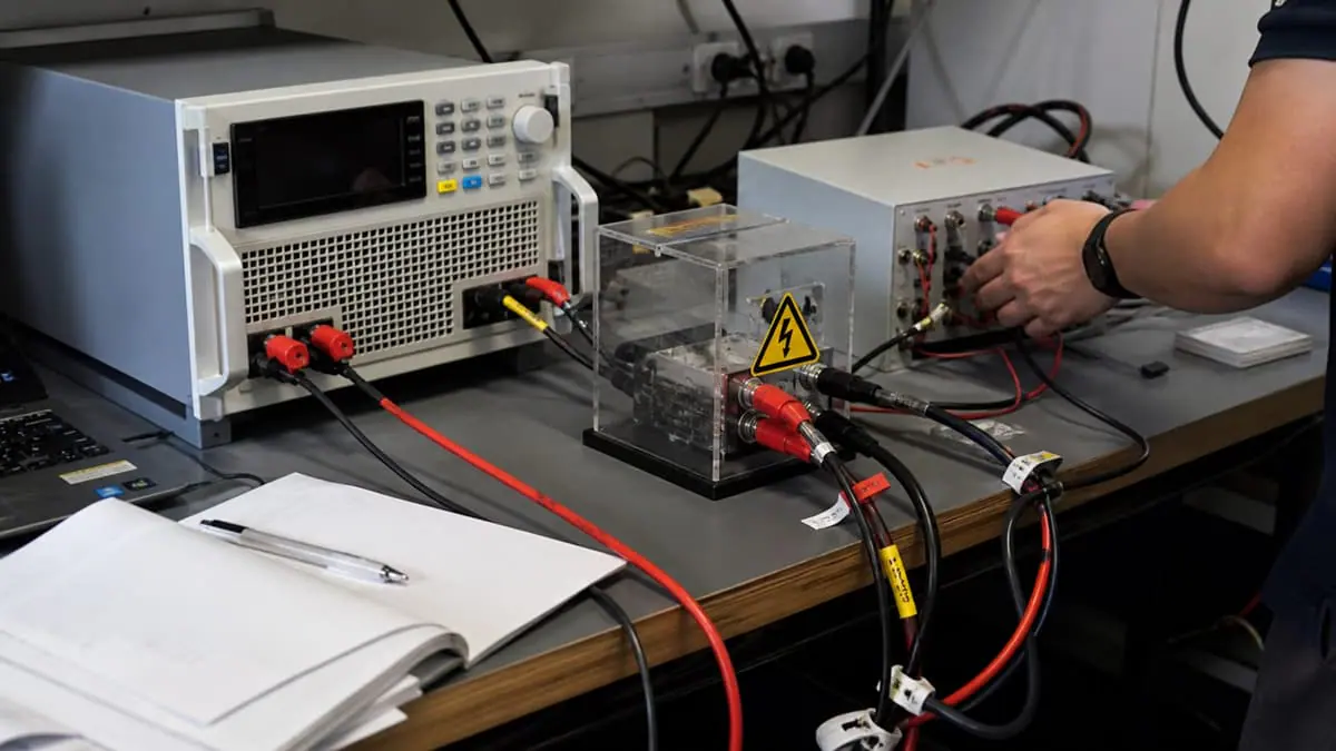
Read the checklist backwards and the bench specifies itself. Grid side: a programmable, four-quadrant source at the PCS’s real connection voltage — able to supply the machine’s full charging import, absorb its full discharging export with the energy returned to the facility mains, and execute the entire event and trajectory library as repeatable sequences; for MV-connected PCS this is precisely the platform class this knowledge centre covers, and for the response-surface campaign its frequency-trajectory programmability is the enabling capability. DC side: battery emulation sized to the PCS’s DC window and power, plus provision for real-battery integration phases. Around both: transfer-resolution measurement at each boundary, the synchronised capture and pipeline of the automation guide, and the safety practices of an MV installation. The scale arithmetic of the sizing guides applies unchanged — the source is rated for the PCS’s apparent-power envelope, both directions, with the reactive capability its Q-services imply.
What this checklist does not cover
Honesty section. This is a converter checklist, not a storage-system one. Cell and battery validation — electrochemical performance, ageing, abuse tolerance, fire safety — is its own discipline with its own standards families and specialist facilities, adjacent to Domain 3 but never replaced by it. System-level round-trip efficiency, augmented by auxiliary loads, HVAC and dispatch behaviour, is a plant-commissioning measurement that the converter’s two efficiency maps inform but do not constitute. Market registration and service qualification are processes with the operator — bench evidence of response behaviour feeds them; the operator’s own verification regime completes them, per the current specifications. And the standing distinction of the compliance guide governs everything above: executing these tests produces evidence; certification and connection approval are granted by bodies and network operators against full current requirements.
Product fit
Where the MVGS fits
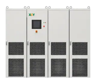
For MV-connected PCS, the XGY MVGS medium-voltage grid simulator is the grid-side instrument the checklist assumes: four-quadrant at the real medium-voltage boundary — full import supplied, full export absorbed with energy returned to the facility mains — executing ride-through, frequency, RoCoF and power-quality campaigns as scripted, repeatable sequences with evidence-grade capture, in the current 5 MVA / 13.8 kV sample configuration. Bench architecture across the five domains, including the DC-side emulation question, is reviewed against your PCS class and market obligations at quote stage.
FAQ
Frequently asked questions
What makes PCS testing different from inverter testing?
Direction and transitions: a PV inverter's tests run one way; a PCS runs every directional test twice — charging and discharging — and adds the transition cases (reversals during events, service commands mid-ride-through) where its control complexity actually lives. Add the DC-side battery boundary with its BMS choreography, and the programme is roughly an inverter campaign squared, not extended.
Should I test against a real battery or a battery emulator?
Both, sequenced: emulation for characterisation, envelope corners, fault-adjacent conditions and regression — where programmability and repeatability are decisive — then the real battery for integration and BMS-coordination verification that no emulator fully reproduces. Programmes that skip emulation fight state-of-charge scheduling all campaign; programmes that skip the real battery meet the BMS's opinions at commissioning.
How is frequency-service response verified?
By commanding realistic frequency trajectories at the grid interface and measuring the PCS's power response — latency, ramp, settling, sustained accuracy — against the applicable service specification's terms; in Australia that framework is AEMO's Market Ancillary Service Specification, and other markets have equivalents. The bench requirement is a source that can program the trajectories and absorb or supply the resulting full-scale power swings.
Why do ride-through tests need to include mid-event transitions?
Because the field does: a storage unit charging when a fault arrives may be commanded — by its own controls or the market — toward discharge during or immediately after the event, and the interaction between ride-through logic, direction reversal and re-synchronisation is where incident reports cluster. Testing ride-through only from steady states verifies the easy cases and leaves the machine's hardest decision unexamined.
Keep exploring
Related technical resources
Related articles
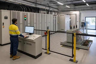
Grid Simulator Fundamentals
What Is a Grid Simulator? A Plain-English Guide
A grid simulator is a programmable AC source that reproduces grid behaviour — sags, swells, harmonics, ride-through events — for lab testing. What it does, who needs one, and how to spec it.
Read article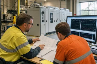
Application Test Guides
How to Test a Medium-Voltage SST at Full Power
The complete SST test bench, block by block: programmable MV grid interface, regenerative DC load or battery emulator, measurement and safety layer — plus the test matrix and an RFQ checklist.
Read article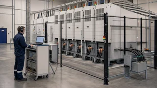
Technical Article
What Is a Solid-State Transformer (SST)? Architecture, Limits, and MVGS Testing
An engineering guide to solid-state transformer architecture, limits, and the role of a medium-voltage grid simulator in full-power SST validation.
Read article