
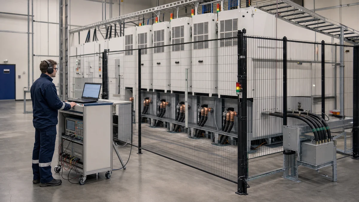
In brief
A solid-state transformer is a power-electronics-based conversion system that performs transformer functions while potentially adding active voltage control, bidirectional power flow, and AC or DC ports. A medium-voltage grid simulator provides the controlled MV electrical boundary needed to test those functions at full power, but it does not replace the SST's other port sources or loads, protection, insulation tests, or safety system.
Key takeaways
- An SST is not simply a conventional transformer made smaller: its topology, isolation method, port arrangement, controls, efficiency, and fault behavior must be evaluated as a complete power-electronic system.
- Use an MVGS when the SST or another DUT connects directly at medium voltage and must experience repeatable voltage, frequency, phase, unbalance, ride-through, or regenerative power-flow conditions.
- A complete SST bench also needs the correct LVAC or LVDC source/load, MV switchgear, grounding, protection, synchronized measurement, cooling, interlocks, and verified discharge states.
- No single cited standard certifies every SST or MVGS application; the applicable grid code, converter safety rules, product requirements, and contractual acceptance criteria must be selected for the actual project.
A solid-state transformer is better understood as a controlled power-conversion system than as a drop-in electronic replacement for every conventional transformer. A traditional electromagnetic transformer changes AC voltage through magnetic coupling and provides galvanic isolation when designed for it. An SST inserts one or more controlled converter stages, which may add regulated AC or DC ports, bidirectional power flow, reactive-power control, fault response, communications, and coordination with storage or renewable sources.
That additional functionality comes with additional engineering obligations. Semiconductor voltage stress, switching losses, magnetics, insulation coordination, thermal management, protection, controls, software, cyber-physical interfaces, and failure states all become part of the design. The U.S. Department of Energy roadmap does not support a blanket claim that SSTs are automatically more efficient, more reliable, or less expensive than conventional transformers. An SST is justified when its controllable functions or port architecture create enough system value to offset its complexity.
What counts as a solid-state transformer?
There is no single circuit that defines every SST. A common multi-stage architecture contains an MV AC/DC front end, an isolated DC/DC conversion stage, and an LV AC and/or DC output stage. Other architectures combine stages, use different isolation arrangements, or expose more than two power ports. Many SSTs use a higher-frequency magnetic link to reduce the size of magnetic components, but “solid-state” does not mean that all magnetic isolation disappears, and the exact isolation method must be stated rather than assumed.

| Architecture family | Functions commonly combined or separated | Engineering consequence to verify |
|---|---|---|
| Single-stage or direct conversion | Input conversion, isolation and output synthesis are largely combined | May reduce intermediate energy-storage stages, but modulation range, isolation implementation, port flexibility and fault control are tightly coupled |
| Two-stage | One controlled conversion boundary is followed by an isolated or output conversion boundary | Can expose a useful DC link or simplify one control task; the actual isolation location and bidirectional envelope still depend on topology |
| Three-stage | MV AC/DC front end, isolated DC/DC stage and LV DC/AC output are separately controlled | Offers more control and port freedom, while adding semiconductors, gate drives, stored-energy states, cooling loads and coordinated failure modes |
Stage count is only a taxonomy. It does not establish efficiency, isolation quality, power density, reliability, fault current, or compliance. Those properties come from the released circuit, devices, controls, construction, cooling, protection, and evidence at stated operating points.
An SST requirements document should identify at least:
- every AC and DC port, its nominal and maximum voltage, current, power, grounding, and isolation relationship;
- allowed source and sink directions, active and reactive power range, overload duration, and transition through zero power;
- voltage and frequency control modes, grid-following or grid-forming behavior, and any islanding or resynchronization claim;
- DC-link and internal stored-energy behavior during startup, shutdown, current limiting, and faults;
- insulation class, clearances, creepage, surge and impulse requirements, partial-discharge method where applicable, and protective-device coordination;
- efficiency, loss, thermal, acoustic, cooling, communications, measurement, and report requirements at defined operating points.
The useful distinction is functional: an SST can actively shape power flow and expose controlled ports that a passive transformer alone does not provide. The tradeoff is that every claimed function needs a test condition, measurement plane, uncertainty statement, and pass criterion.
| Decision factor | Typical two-winding line-frequency transformer | Solid-state transformer |
|---|---|---|
| Voltage conversion and regulation | Fixed turns ratio; tap changers and external equipment may provide discrete or system-level regulation | Converter controls may provide continuous regulation within defined voltage, current and thermal limits |
| Power direction and reactive power | AC power can physically flow either way when the surrounding network permits, but the transformer does not independently command P or Q | Semiconductor stages may actively control signed P and Q within their validated envelope |
| DC and multi-port integration | Requires external converters for native DC or additional controlled ports | May expose regulated DC and multiple AC/DC ports as part of the design |
| Isolation and magnetics | Line-frequency magnetic isolation with mature protection and service practices; an autotransformer is a different case and does not provide galvanic isolation | Often uses an isolated medium-frequency stage; winding stress, common-mode behavior and partial discharge require topology-specific evidence |
| Fault behavior | High prospective current is usually limited by network and leakage impedance, with established protection practices | Active current limiting is possible, but semiconductor survival, stored energy, DC interruption and control failure add protection states |
| Efficiency, size and life | Mature field evidence; losses and footprint depend on rating, materials and loading | No automatic advantage: each conversion stage, auxiliary, cooling system and operating point affects loss, size and lifetime |
| Best-fit question | Is robust voltage transformation and isolation sufficient? | Do controllable ports, bidirectional conversion or grid-support functions justify the added electronics and lifecycle burden? |
What is an MVGS?
In this article, MVGS means medium-voltage grid simulator. It is a programmable power test system that establishes a controlled medium-voltage AC boundary for a device under test. Depending on configuration, it can set voltage, frequency, phase, unbalance, ramps, steps, ride-through events, harmonics, and source/sink power conditions. Synchronized measurements, programmed settings, and protection states must be captured by the overall test system; they should not be assumed from the MVGS label.
The name is descriptive, not a guarantee of a universal feature set. IEC TS 62749:2026 uses 1 kV < U_N <= 35 kV for medium voltage within that document and explicitly notes that regional boundaries can differ. Likewise, “grid simulator” does not automatically mean regenerative, four-quadrant, weak-grid capable, independently controlled per phase, or suitable for every grid-code event. Those functions have to appear in the released equipment configuration and be demonstrated at the DUT connection point.
| Equipment class | Primary controlled boundary | Can supply the DUT? | Can accept DUT power? | Typical decision use |
|---|---|---|---|---|
| Programmable AC source | Voltage, frequency, and supported waveform range | Yes | Do not assume it | Powered equipment input tests where the DUT does not export energy |
| AC electronic load | Current, P/Q, power factor, impedance, or load profile | Not as the DUT voltage source; some four-quadrant loads exchange reactive or instantaneous power | Yes, within its load and regenerative envelope | UPS, generator, inverter, and AC-source output tests |
| Regenerative grid simulator | Programmable grid voltage plus bidirectional active/reactive power behavior | Yes | Yes, within its sink envelope | Grid-connected converters, PCS, V2G, and regenerative DUTs |
| Medium-voltage grid simulator | A programmable grid boundary at the project’s MV class | Yes | Configuration-dependent; four-quadrant platforms can | SST, MV PCS, MV UPS, renewable converters, and MW-scale integrated tests |
| Real-time simulation / PHIL | Simulated network and controller interaction, with a power interface for PHIL | Through the power interface | Through the power interface | Control development and network-interaction studies beyond a standalone source model |
The safe procurement rule is simple: if the data sheet does not state bidirectional, sink, or regenerative operation at the required voltage, current, duration, and power factor, do not plan to return DUT energy into that source.
Where an MVGS sits in an SST test bench
An MVGS establishes the SST’s medium-voltage boundary. It is not the whole bench. The SST’s other port may need a regenerative LVAC source/load, a DC source, a battery emulator, an electronic load, or a combination of these. Between each high-energy element are switchgear, grounding, protection, pre-charge or discharge functions, access control, emergency stop, cooling, communications, and synchronized measurement.
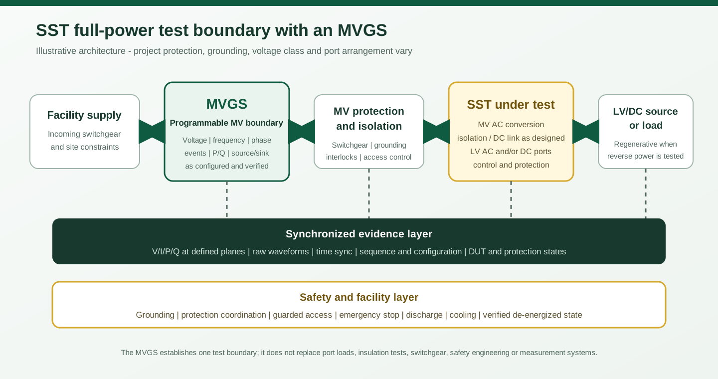
A direct-output MVGS and a low-voltage source followed by a step-up transformer can both be valid architectures. In some projects the transformer option can reuse existing assets, but the transformer, switchgear, floor area, losses, calibration, protection, and integration can also increase total installed cost. It adds its ratio, leakage impedance, saturation, vector group, grounding, bandwidth, inrush, losses, thermal behavior, and protection to the delivered waveform. Direct MV output is valuable when those effects would obscure the event under study or when the actual MV interface must be exercised. Neither architecture should be selected by label alone: measure the required waveform at the SST terminals.
The opposite port must be programmed as deliberately as the MV port. A DC source/load or battery emulator needs the correct voltage window, source/sink current, dynamic load profile, state boundaries, stored-energy limits and emergency response. High-value tests combine an MV event with an LV or DC load step to expose DC-link energy management and cross-port control. A steady-state efficiency map and a thermal soak remain necessary, but neither substitutes for those coupled dynamic tests.
Four-quadrant and regenerative operation
“Four-quadrant” is unsafe as a requirement unless the coordinate system is named. Converter documentation may describe voltage-current quadrants, while AC grid-testing teams often use a signed P-Q capability map. These are related ways of describing reversible operation, but they are not interchangeable vendor definitions. This article uses a P-Q test matrix: positive active power means MVGS-to-SST, negative active power means SST-to-MVGS, and the agreed reactive-power sign distinguishes the two Q directions. The RFQ and acceptance test must verify continuous and time-qualified voltage-current and P-Q envelopes instead of relying on the phrase alone.
If the SST exports power through its MV port, the test bench needs a documented sink path. A regenerative MVGS converts accepted energy back toward its facility interface, subject to converter loss, auxiliaries, grid-side limits, local loads, protection, and site rules. “Regenerative” therefore does not mean that all energy reaches a utility meter, that export is permitted, or that the facility only needs to be sized for losses.
For a defined measurement plane and the sign convention above, energy accepted from the SST can be calculated as:
E_absorbed,plane = integral(max(-P_plane(t), 0) dt).
For example, a fictional SST delivering 2.4 MW in the negative-P direction for 12 minutes transfers 2.4 MW x (12/60) h = 0.48 MWh across that selected plane. This is not a customer result, MVGS efficiency figure, facility-export value, or utility-credit figure. To report energy returned at the facility interface, measure again at that interface; converter loss, cooling, auxiliaries, transition periods, reactive current, local loading, reverse-flow protection, and metering separate the two planes.
What should an SST test matrix cover?
The matrix should link every claimed function to a starting state, programmed condition, measurement, allowed response, recovery window, and retained evidence. The following is a planning baseline, not a universal certification programme.
| Test area | Controlled condition | Evidence to retain | Hold or reject when |
|---|---|---|---|
| Pre-energization | Grounding, phase sequence, insulation boundary, settings, cooling, access and interlocks | Approved one-line, settings export, continuity and interlock records, verified-safe checklist | An energized state is possible before access, grounding, protection and discharge logic are proven |
| Steady state | Voltage, current, frequency, P/Q points, port direction and thermal dwell | Synchronized port measurements, losses, temperatures, waveform and configuration | Only a nominal MVA label is demonstrated or a required operating point is omitted |
| Bidirectional operation | Forward/reverse active power, both reactive directions and zero-crossing transitions | P/Q trajectory, DC-link state, current limits, facility response and recovery | Returned energy has no valid sink path or transitions trigger undocumented protection behavior |
| Grid disturbance | Voltage/frequency ramps and steps, phase jump, unbalance, harmonics and sequence timing | Programme file plus measured terminal waveform and SST state | A named event is stored without proving what reached the DUT terminals |
| Ride-through | Project-defined LVRT, HVRT or ZVRT profile and recovery | Residual voltage, duration, phase selection, current response, P/Q support, trip state and recovery time | A generic curve is used without confirming the applicable grid rule and DUT mode |
| Grid strength | Defined impedance or validated emulator/PHIL method over the frequency range of interest | Impedance target, achieved response, operating point, oscillation damping and model version | A stiff voltage source is described as weak-grid validation without an evidenced impedance method |
| Mode transition | Grid-following/forming, islanding and resynchronization only when claimed | Command sequence, phase/frequency alignment, transient energy and protection state | Unsupported modes are added to the plan or synchronization limits are undefined |
| Fault recovery | Communication loss, sensor invalidity, over-limit, contactor mismatch, emergency stop and restart | Trigger, ordered state transitions, discharge time, alarm history and reset authority | Automatic restart can occur before hazardous energy is verified removed |
Internal SST failure mechanisms need an explicit coverage boundary; a programmable MV waveform alone cannot close them.
| Mechanism to investigate | What the MVGS can contribute | What remains separate or jointly controlled |
|---|---|---|
| MV-port short circuit and active current limiting | Reproducible pre-fault operating point and a validated source-impedance/event boundary within the MVGS rating | Purpose-built fault insertion or short-circuit source when required, protection coordination and safe fault-energy limits |
| LVAC or DC-port fault | Maintains or changes the MV-side condition while the SST responds | Opposite-port fault equipment, DC interruption without a natural current zero, contactor/breaker evidence and discharge verification |
| Module voltage balance and parallel current sharing | Repeats grid and P/Q conditions that stress balancing controls | Per-cell measurements, internal telemetry, injected sensor/communication faults and vendor-defined safe limits |
| Cell bypass, communication loss, derating and restart | Holds a controlled external boundary during the state transition | Fault injection, bypass hardware, redundancy logic, restart authority and proof that stored energy is safe |
| Thermal imbalance | Supplies repeatable operating envelopes and disturbances | Calibrated temperature channels, cooling manipulation, loss mapping, soak time and component-specific limits |
| Insulation, common-mode and leakage-current behavior | Applies verified operating-voltage waveforms at the MV port | Dedicated impulse and power-frequency withstand tests, IEC 60270 partial-discharge measurement where applicable, plus topology-specific common-mode instrumentation |
| Combined grid event and output load step | Reproduces the programmed MV-side event | Synchronized LV/DC source-load transient, DC-link energy limits and a common trigger across every measurement plane |
Ride-through and weak-grid testing are different problems
A voltage dip or frequency event can be generated by a stiff programmable voltage source. Weak-grid behavior concerns the interaction between the DUT controller and network impedance. A common screening quantity is short-circuit ratio:
SCR = S_sc / S_rated
where S_sc is short-circuit apparent power at the defined connection point and S_rated is the selected DUT or plant rating under the project’s convention. The formula is easy; reproducing the relevant impedance magnitude, angle, frequency dependence, operating point, background harmonics, and protection behavior is not.
Do not infer weak-grid capability from the words “grid simulator.” The bench may need physical impedance, a converter control mode whose impedance has been validated over the required frequency range, or power-hardware-in-the-loop. NREL’s controllable grid interface publications and current ARIES facility description show that balanced and unbalanced fault events, strong/weak-grid conditions, islanding, reactive power, hardware-in-the-loop, and power-hardware-in-the-loop can be combined in purpose-built research platforms. That evidence establishes technical feasibility; it does not prove that every MVGS configuration provides the same modes.
Illustrative sizing calculation - not an XGY configuration
Assume a fictional balanced three-phase test point of 3 MVA at 11 kV line-to-line. The nominal line current is:
I_L = S / (sqrt(3) x V_LL) = 3,000,000 / (sqrt(3) x 11,000) = 157 A approximately.
That result is only one operating point. It does not establish the current needed during a depressed-voltage ride-through event, harmonic injection, unbalance, overload, reverse power, or reactive-power support. A valid envelope also defines per-phase current, neutral current if present, continuous and time-qualified power, current limit, voltage-dependent power capability, cooling, and recovery. It then checks those points against the selected product’s source and sink I-V boundary rather than using MVA alone.
When should you use an MVGS?
An MVGS is usually justified when several of these conditions are true:
- the SST, PCS, UPS, inverter, drive, or other DUT connects directly at the project’s medium-voltage boundary;
- correct operating voltage is needed for insulation, grounding and common-mode interaction; correct current, loss and cooling conditions are needed for thermal questions; and defined fault energy and source impedance are needed for protection questions. These conditions do not always occur simultaneously, while impulse, power-frequency withstand, partial-discharge and BIL qualification require their specified dedicated methods and equipment;
- the DUT exports power or requires both active and reactive source/sink operation;
- dangerous or utility-disruptive voltage, frequency, phase, unbalance, harmonic, or ride-through events must be repeated safely;
- the project needs synchronized, repeatable evidence linking the commanded event to the delivered terminal waveform and DUT response;
- a scaled bench or simulation cannot answer the remaining integration and acceptance questions.
An MVGS is often unnecessary when the DUT is low voltage, unidirectional, and adequately covered by a programmable AC source; when early controller work can be completed with model-in-the-loop, controller-HIL, or a lower-power platform; or when a characterized LV source and transformer reproduce the required DUT-terminal condition. It is also the wrong tool for tasks such as lightning impulse, BIL/withstand, partial discharge, high-current short-circuit interruption, radiated EMI, environmental qualification, or mechanical testing unless those functions are provided by separate purpose-built equipment.
Facility and acceptance boundaries
At MV and megawatt scale, the facility is part of the test system. The scope should identify incoming voltage and available capacity, switchgear ratings, fault level, protective coordination, grounding, cable routes and terminations, access zone, arc-flash and work controls, floor loading, transport path, cooling, ventilation, acoustic limits, fire strategy, communications, time synchronization, permitted reverse flow, and the behavior of local generators, transformers, UPS systems, or site export controls.
Factory acceptance and site acceptance close different risks. FAT can prove supplier-controlled hardware, software, sequence files, interlocks, reports, and simulated interfaces. SAT proves the installed supply, grounding, cables, cooling, protection, emergency circuits, facility-side regeneration, communications, and agreed representative DUT or substitute load conditions. Neither should mark an untested dependency as passed.
The report should retain raw waveform or time-series data, measurement plane, sample rate and bandwidth, trigger alignment, instrument and transducer identifiers, calibration status, corrections, uncertainty components, programmed sequence, configuration hash or version, DUT state, operator, timestamps, and decision rule. Display resolution is not measurement uncertainty, and a screenshot is not a substitute for traceable data.
Standards and claim boundaries
There is no single published standard in the references below that certifies every SST architecture. IEEE P3105 is currently listed by IEEE as an Active PAR, so it must not be represented as an issued IEEE 3105 standard. IEC 62477-2 provides safety requirements for power-electronic converter systems within its voltage scope; it does not by itself certify a complete SST installation. IEEE 1547.1 applies when the equipment is within the defined DER interconnection scope, not merely because an SST connects to a grid.
Likewise, familiar IEC 61000-4-11 and IEC 61000-4-34 voltage-dip methods address equipment connected to low-voltage supply networks within their stated current scopes. They are not generic MV SST qualification standards. The applicable grid code, installation rules, converter and equipment safety standards, insulation requirements, customer specification, jurisdiction, test laboratory role, and contractual evidence must be determined for the actual project.
IEC 60071-1 provides insulation-coordination principles above 1 kV; IEC 60060-1:2025 covers specified high-voltage dielectric test methods; and IEC 60270:2025 covers charge-based partial-discharge measurement. Their inclusion defines why these are separate engineering and evidence scopes. It does not create a universal SST test sequence or imply that normal MVGS operation performs those tests.
Source-to-claim map
| Claim area | Primary-source basis | Boundary retained in this article |
|---|---|---|
| SST/SSPS functions, applications and technology challenges | U.S. DOE Solid State Power Substation Technology Roadmap | No universal efficiency, cost, size, maturity or reliability advantage is claimed |
| Meaning of MV in a current public-network document | IEC TS 62749:2026 | The above-1-kV-through-35-kV boundary is document-specific and regional definitions may differ |
| Full-power controllable MV grid research | NREL Controllable Grid Interface and ARIES capabilities | One NREL platform demonstrates feasibility; it is not used as an XGY product specification |
| XGY MVGS topology and configurable range | Current XGY MVGS selection guide | Figures remain product- and configuration-specific; no standard compliance is inferred |
| MV power-converter safety context | IEC 62477-2 | Applicability and additional equipment, installation and jurisdictional requirements remain open |
| Insulation coordination, dielectric tests and partial discharge | IEC 60071-1, IEC 60060-1:2025 and IEC 60270:2025 | Separate methods and product-specific limits remain necessary; normal MVGS operation is not represented as these tests |
| Emerging SST design guidance | IEEE P3105 project page | P3105 is identified as an Active PAR, not a published compliance standard |
| DER conformance testing | IEEE 1547.1-2020 | Cited only when the SST or integrated system falls within its defined DER scope |
| Measurement uncertainty discipline | NIST Technical Note 1297 | No project-specific uncertainty value, conformity decision rule, or accreditation claim is supplied |
The practical decision is not “SST or transformer” or “MVGS or no MVGS” in isolation. First define the functions and evidence the project needs. Then select the smallest test architecture that can reproduce the electrical boundary, energy flow, safety states, and measurement quality without hiding the behavior being evaluated.
Product fit
Where the XGY MVGS fits in an SST test bench
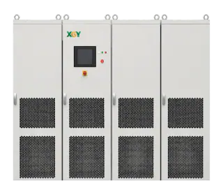
The XGY MVGS Series is the direct medium-voltage product starting point for SST, PCS, and other megawatt-scale power-electronics projects that require a four-quadrant programmable MV boundary. Its current selection guide lists configurable 5 kV to 35 kV direct output and 1 MVA to 10 MVA standard capacity with project expansion to 20 MVA and above; final voltage, current, waveform, cooling, protection, site-regeneration, and acceptance capability remain configuration-specific and must be reviewed against the DUT and facility.
FAQ
Frequently asked questions
What is a solid-state transformer in simple terms?
A solid-state transformer uses controlled power-electronic conversion to change voltage or power form and can add functions such as bidirectional power flow, regulated AC or DC ports, and grid support. Many designs include an isolated high- or medium-frequency conversion stage, but SST topology and isolation are design-specific rather than universal.
What is an MVGS?
In this article, MVGS means medium-voltage grid simulator: a programmable test system that establishes a controlled MV electrical boundary and reproduces defined voltage, frequency, phase, unbalance, disturbance, and source/sink conditions. The exact capabilities must be confirmed from the selected configuration and measured at the DUT connection point.
When is an MVGS needed for SST testing?
Use an MVGS when the SST has a real medium-voltage port and the test must reproduce full-power steady-state operation, reverse power, reactive power, ride-through, frequency events, unbalance, phase changes, or other controlled grid conditions. Early control development may instead use simulation, HIL, or a lower-power bench.
Can a low-voltage AC source and step-up transformer replace an MVGS?
Sometimes. It can be a valid option when the transformer, grounding, protection, bandwidth, saturation, sequence behavior, and delivered DUT-terminal waveform are characterized for the required tests. Direct MV output is more useful when the output transformer would obscure the condition being studied or when the actual MV interface must be validated.
Does testing with an MVGS certify an SST?
No. An MVGS can generate controlled conditions and support traceable test evidence, but certification or compliance depends on the applicable standard, jurisdiction, accredited or accepted process, calibrated measurement chain, decision rule, and complete evidence package.
Keep exploring
Related technical resources
Related articles
Grid Simulator Fundamentals
What Is a Grid Simulator? A Plain-English Guide
A grid simulator is a programmable AC source that reproduces grid behaviour — sags, swells, harmonics, ride-through events — for lab testing. What it does, who needs one, and how to spec it.
Read article
Application Test Guides
How to Test a Medium-Voltage SST at Full Power
The complete SST test bench, block by block: programmable MV grid interface, regenerative DC load or battery emulator, measurement and safety layer — plus the test matrix and an RFQ checklist.
Read article
Technical Article
Regenerative AC/DC Source Planning for EV and Power Electronics Test
A planning guide for regenerative AC/DC sources used in EV chargers, inverters, grid simulation, and power electronics validation.
Read articleRelated products
Power Supplies
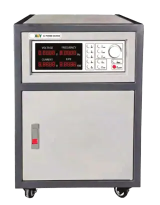
AC301SHP / AC303SHP Series High-Power AC Grid Simulator Power Supply
XGY AC301SHP / AC303SHP is a high-power programmable AC grid simulator and power supply series for industrial testing, EV motor and charger validation, large appliance testing, and facility-level power simulation.
View product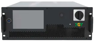
Power Supplies
GXC804B-5K Series Regenerative AC/DC Power Source
XGY GXC804B-5K is an AC/DC power source and regenerative electronic load for grid simulation, RLC/RCD load simulation, BiPolar DC operation, and HIL testing. The 5 kW (rated power) model provides 0 to 450 V L-N AC output at 0.01 to 70 Hz and 0 to 636 V DC output in a compact 4U chassis.
View product