
In brief
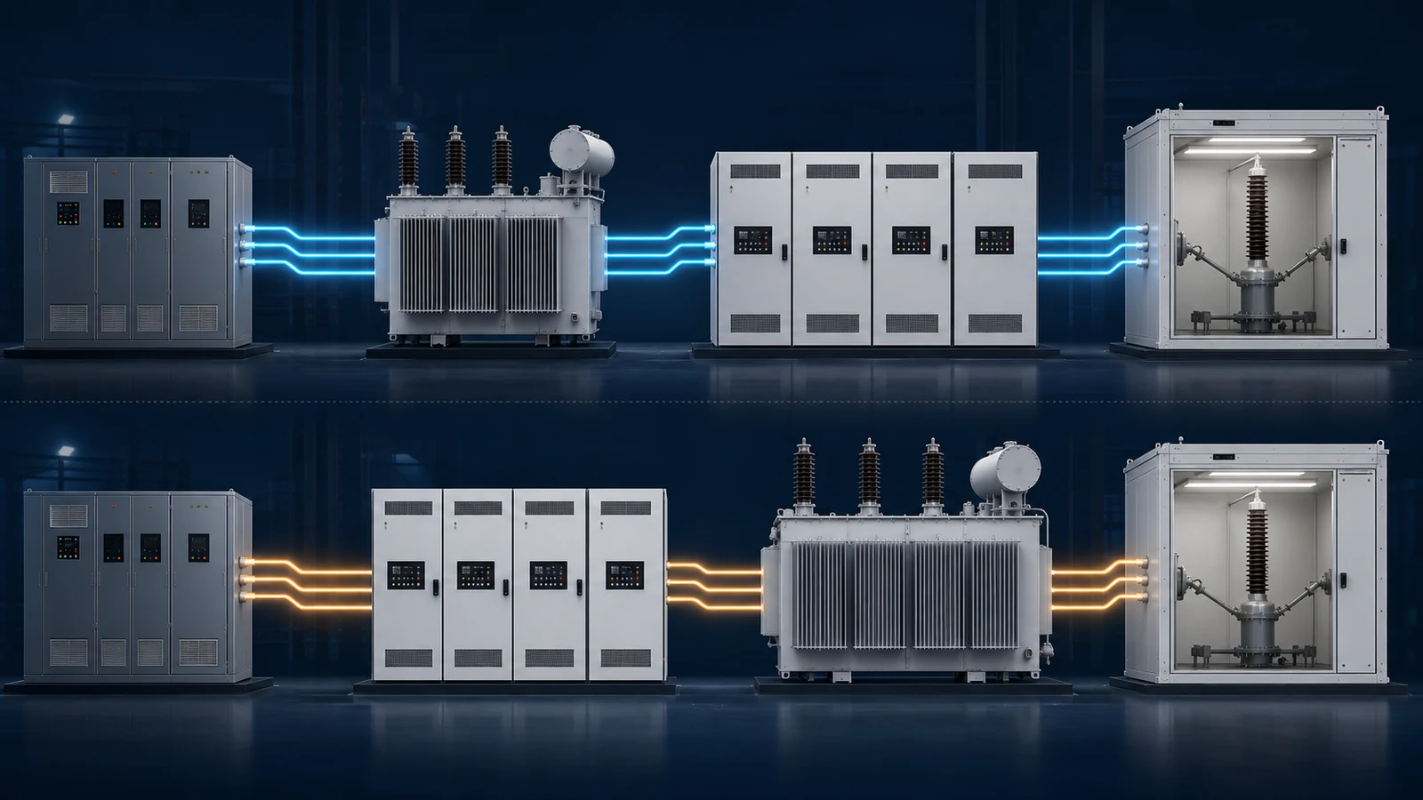
Front-end isolation places the transformer at the facility input and uses the downstream converter to synthesise the medium-voltage output. Back-end isolation places a step-up transformer between a lower-voltage converter and the DUT. Neither arrangement makes a controller command identical to the DUT-terminal waveform: output filters, control bandwidth, transformer or cable impedance, DUT loading, protection states, and configuration all affect what is delivered. The right architecture is the one whose complete source-to-DUT path can meet the project's measured waveform, grounding, protection, and repetition criteria.
Key takeaways
- Transformer placement changes the measurement boundary; it does not remove the need to verify the voltage and current actually delivered at the DUT terminals.
- A back-end transformer can be a practical, economical route when its ratio, vector group, impedance, frequency response, saturation behaviour, and earthing effects are characterised for the required tests.
- Front-end isolation can remove output-transformer-specific filtering and flux-reset constraints, but converter filters, control bandwidth, load dynamics, thermal limits, protection, and sequence settings still constrain event fidelity and repetition rate.
- Grounding and fault tests require a reviewed earthing single-line, common-mode measurement plan, protection-coordination study, and explicit fault-energy boundaries; isolation placement alone proves none of them.
- Architecture should be accepted at the DUT terminals through agreed FAT and SAT evidence, not from topology labels or unloaded controller screenshots.
Isolation placement changes the test boundary
An MV test bench needs a defined separation, earthing, switching, and protection concept, but that does not mean every installation must contain the same dedicated transformer in the same position. The applicable law, equipment standards, facility design, DUT topology, and project risk assessment decide the required isolation and protective measures. For the two architectures compared here, the practical question is narrower: does the principal isolation transformer sit before the programmable converter or between that converter and the device under test (DUT)?
That placement changes the source-to-DUT transfer path. In a back-end architecture, the low-voltage converter command passes through its output filter, cables or buswork, a step-up transformer, MV switchgear, and the test connection before reaching the DUT. The transformer’s leakage impedance, winding resistance, vector group, magnetising branch, capacitance, residual flux, and thermal state therefore participate in every event. In a front-end architecture, the transformer is on the facility side and the downstream converter synthesises medium voltage. The DUT-side path no longer contains that output transformer, but it still contains converter filters, control delay, switching limits, cables, switchgear, transducers, and protection.
This leads to the article’s most important boundary: a waveform command is not evidence of the waveform at the DUT terminals. A direct-MV architecture can avoid output-transformer-specific filtering, phase displacement, and flux behaviour. It cannot make power electronics infinitely fast or make a finite source ignore load current. Control bandwidth, modulation headroom, output-filter resonance, cable impedance, current limits, thermal limits, protection states, and configuration determine how closely the terminal waveform follows the request.
The same discipline applies to repetition. Moving the transformer to the input can remove a wait that was required specifically to restore output-core flux or thermal margin. It does not remove waits imposed by DC-link recovery, semiconductor temperature, facility regeneration, protection reset, discharge verification, sequence guards, or the DUT itself. Architecture changes the constraint set; it does not abolish constraints.
The two architectures in the same engineering language
| Architecture | Simplified power path | Main benefit to verify | Main limitation to characterise |
|---|---|---|---|
| Back-end isolation | Facility supply -> LV programmable converter -> step-up transformer -> MV DUT | Reuse of a proven LV source; potentially lower capital cost for a bounded programme | Transformer transfer function, flux margin, vector group, voltage regulation, zero-sequence path, and interaction with source protection |
| Front-end isolation | Facility supply -> input isolation transformer -> direct-MV converter -> MV DUT | No output transformer in the programmed-event path; potentially greater freedom for dynamic events and DUT-side earthing | Converter/filter bandwidth, modulation and current envelope, cable and load interaction, common-mode behaviour, protection, and configuration-specific limits |
The terms describe placement, not quality. A carefully characterised back-end system can be a valid instrument for steady-state, slow-transient, or otherwise bounded tests. A poorly commissioned direct-MV system can produce unusable evidence. Conversely, if a required event needs an edge, spectral component, zero-sequence state, or repetition rate outside the verified output-transformer envelope, no amount of controller resolution makes the back-end chain fit that row of the test matrix.
The comparison must therefore use one measurement boundary for both candidates: the defined DUT connection point. Quotes should show the complete single-line from facility connection to DUT, identify every switchable earthing state, and state whether published accuracy or transition figures were measured internally, at unloaded output terminals, or at the proposed loaded DUT boundary. Only the last of those directly answers the application question.
Architecture decision matrix
Use the matrix as a screening tool, then replace its qualitative entries with project limits and measured evidence.
| Test need | Back-end isolation is a reasonable candidate when | Front-end isolation deserves priority when | Evidence needed before selection |
|---|---|---|---|
| Steady-state withstand or efficiency mapping | Ratio, regulation, heating, and phase displacement are acceptable and included in the measurement model | Direct connection simplifies the setup or the converter already matches MV | Loaded voltage/current accuracy, loss allocation, temperature, and uncertainty |
| LVRT, HVRT, or ZVRT | Measured depth, edge, dwell, recovery, point-on-wave, and repetition all meet the test plan | Output-transformer response or flux margin prevents those limits from being met | DUT-terminal waveform for worst-case load, repeated runs, source-limit and protection logs |
| Harmonic or interharmonic injection | The complete chain transfers each required component within amplitude and phase tolerance | Transformer response, resonance, or heating narrows the required spectrum | Frequency sweep plus loaded spectral measurements and transducer correction |
| Unbalance or single-phase-to-earth events | Vector group, neutral, zero-sequence impedance, insulation, and protection support the intended state | A configurable converter output can establish the required phase and earthing state | As-built earthing diagram, zero-sequence model, residual/common-mode capture, fault study |
| Repetitive automated campaigns | Verified reset and thermal intervals still meet throughput needs | Output-transformer recovery is the dominant bottleneck | Long sequence run with temperatures, DC-link state, limits, interlocks, and timestamps |
| Existing LV source reuse | Source ratings, transformer duty, measurement, and protection upgrades still produce acceptable total cost | Required modifications approach the cost or risk of a direct-MV platform | Lifecycle cost, unavailable-test list, commissioning effort, and acceptance risk |
No row awards a topology an automatic pass. The decision is conditional on the selected ratings, output network, DUT operating point, and acceptance tolerances. A topology label is only the start of the requirements conversation.
Characterise the complete source-to-DUT path
Characterise the power path, not only the transformer nameplate
For a back-end system, begin with ratio, polarity, vector group, taps, rated power, impedance, losses, insulation level, cooling, and temperature rise. Then add the quantities that dynamic testing exposes: no-load current, residual-flux sensitivity, inrush, saturation margin for asymmetric volt-seconds, frequency response across the commanded spectrum, zero-sequence impedance where relevant, winding and screen capacitance, and voltage regulation versus current magnitude and power factor. IEC 60076-8 and IEC 61378-3 provide authoritative application context, but the project’s unusual duty cycle and converter waveform still need supplier review.
Treat the LV source and transformer as one controlled plant. The source’s voltage loop may have been tuned for a different load. Transformer leakage and cable capacitance can introduce poles or resonances; an output sine filter may add more. Current limiting can change a nominal voltage-source command into a current-constrained response during the exact ride-through event being assessed. Characterisation should cover no load, a representative passive load, and the real DUT operating states that create the highest current, reactive power, distortion, or control interaction.
For a front-end system, deleting the output transformer does not delete this work. Record the converter switching and control rates where disclosure is appropriate, output-filter topology, usable small- and large-signal bandwidth, voltage and current envelope versus operating voltage, modulation headroom, per-phase cross-coupling, common-mode voltage, cable-length limits, and stability restrictions for capacitive or actively controlled loads. Repeat the terminal tests after material firmware, filter, cable, or protection-setting changes.
Useful tests include a low-amplitude swept-sine or multisine response where safe, step responses at several load currents, point-on-wave changes, programmed dips and swells, phase jumps, and the exact harmonic combinations in the test plan. A small-signal sweep does not by itself predict a deep voltage dip at full current; both linear characterisation and large-signal event tests are needed.
Characterise the measurement chain independently
The terminal waveform is only as trustworthy as the sensors and acquisition path. Document the voltage divider or transformer, current transducer, burden, cable, isolation interface, digitiser range, sampling rate, anti-alias filter, time synchronisation, scaling, phase correction, and calibration status. IEC 61869-1 addresses relevant high-voltage instrument-transformer error and bandwidth concepts; the specific transducer technology and applicable part of the series still matter. IEC 61000-4-30 provides methods context for power-quality parameters, but it does not replace a test-specific uncertainty budget.
At minimum, the uncertainty budget should consider ratio error, phase error, bandwidth and settling, digitiser resolution, noise, channel skew, probe loading, common-mode rejection, temperature, cable position, and data-processing windows. A channel suitable for 50 Hz RMS may be unsuitable for a 1 ms edge. A wide-band divider may capture the edge but have a different uncertainty for RMS and harmonics. Use separate channels or validated processing when one chain cannot satisfy every measurand.
Define each acceptance metric before testing. For a dip, that may include pre-event RMS, point on wave, transition time, residual voltage, dwell duration, phase-angle behaviour, overshoot, recovery trajectory, and post-event settling. For harmonic injection, define the analysis window, fundamental tracking, amplitude and phase tolerance, distortion contributed by the DUT, and the frequency range over which transducer correction is valid. Save raw time-series data as well as summary values so a reviewer can reproduce the decision.
Grounding and protection are architecture requirements
Prove each earthing state on the as-built single-line
Isolation can permit the test-side earthing arrangement to be defined independently of the facility, but transformer placement alone does not establish a safe or useful neutral. For every planned state - solidly earthed, impedance earthed, unearthed, or a temporary single-phase-to-earth condition - show the intended current path and every unintended parallel path. Include transformer vector group, neutral conductors, earthing resistor or reactor, cable screens, filter capacitors, surge devices, measurement dividers, auxiliary supplies, cabinet bonding, DUT EMI capacitors, and communication shields.
An output transformer fixes important parts of that network through its winding connection and capacitance. A direct-MV converter may offer more programmable freedom, yet its cells, filters, sensors, and protection still create common-mode paths. Measure neutral displacement, residual voltage and current, common-mode voltage, protective-conductor current, and relevant touch or transferred potentials under controlled conditions. Do not infer a ground-fault capability merely from independent phase-voltage control.
Coordinate protection around credible fault energy
The protection review should cover normal operation, a DUT-side short circuit, single-phase and phase-to-phase faults, loss of control power, loss of communications, sensor failure, pre-charge failure, DC-link overvoltage, cooling failure, door or earth-switch interlock operation, emergency stop, and failure of the primary interrupting device. State which device detects each condition, which device interrupts it, the expected clearing sequence, and the energy that can reach the fault before isolation.
For a back-end transformer, leakage impedance may limit current but stored magnetic energy, saturation, source current limiting, and upstream protection coordination affect the actual waveform and clearing time. For a front-end converter, fast electronic current limiting can reduce energy, but only within its validated detection and switching behaviour; it is not a substitute for appropriately rated switchgear and protective bonding. IEC 60204-11 is useful safety context for equipment within its scope, while local law, facility rules, the responsible electrical engineer, and the project hazard study govern the installation.
FAT and SAT acceptance plan
Factory acceptance testing (FAT) should establish that the configured equipment can meet the agreed electrical and control requirements before shipment. Site acceptance testing (SAT) should prove that the installed system - including facility supply, cables, switchgear, earthing, cooling, communications, measurement, and DUT interface - preserves those results or explains any change. A factory waveform does not automatically transfer to a longer site cable or a different grounding network.
The acceptance protocol should contain at least these blocks:
- Configuration baseline. Record serialised power modules, transformer data, filter and cable configuration, firmware, parameter files, protection settings, transducer identities, calibration status, and drawing revisions. Define change control after acceptance.
- Static electrical checks. Verify ratio, phase sequence, vector relationship where applicable, polarity, earthing continuity, insulation and safety checks required by the approved procedure, no-load output, loaded regulation, current limits, and thermal steady state at agreed operating points.
- Dynamic waveform checks. Execute the specified ride-through, recovery, phase-jump, frequency-ramp, unbalance, and spectral cases. Measure at the contractual DUT boundary under the agreed load or validated load emulator. Capture controller command and internal feedback only as supporting channels.
- Repetition and endurance. Run enough consecutive events to reveal flux accumulation, DC-link drift, thermal derating, protection counters, timing jitter, or DUT reset dependencies. The interval should come from the test matrix, not a generic claim of continuous operation.
- Grounding and protection. Demonstrate each authorised earthing state, interlock, emergency stop, communication-loss response, overcurrent state, and safe discharge or access sequence. Forced-fault tests require a separately approved method and energy analysis.
- Evidence and decision rule. Tie commands, terminal measurements, DUT response, equipment status, alarms, and protection records to one timebase. Define tolerance, uncertainty, guard band, invalid-run conditions, retest rules, and who signs the result.
FAT and SAT should also define what is not tested. A passed 20% voltage dip at one load does not qualify every dip depth, power factor, cable length, and grounding state. Acceptance is an evidence-backed envelope. Tests outside it require engineering review or additional qualification.
Worked example: an illustrative ride-through decision
The numbers below are hypothetical engineering examples. They are not MVGS specifications, XGY product measurements, customer results, or a substitute for a project study.
Assume a 1 MVA DUT connected at 6.6 kV line-to-line. Its nominal line current is approximately:
I = S / (sqrt(3) x V) = 1,000,000 / (1.732 x 6,600) = 87.5 A
The proposed test requires a balanced dip from 1.0 pu to 0.20 pu, a transition time no greater than 2 ms, a 150 ms dwell, recovery to 1.0 pu, and three repetitions separated by 2 seconds. The project defines transition time from 90% to 10% of the voltage change, requires the dwell measurement to remain between 0.19 pu and 0.21 pu, and invalidates a run if the source enters current limit or protection changes state.
The first trap is current. If the DUT tried to maintain constant apparent power at 0.20 pu, the current request would approach five times nominal, about 437 A. The actual DUT may instead reduce power, current-limit, or trip, but the source architecture cannot be judged without that behaviour. Both candidates therefore need a current-versus-voltage envelope and a loaded test. A 0.20 pu controller command is not proof of 0.20 pu at the terminals.
Candidate A is an existing LV source plus a step-up transformer. Its assumed nameplate leakage impedance is 6%, but that number alone does not predict the event. The team measures its large-signal response at representative current and power factor, checks point-on-wave sensitivity, records residual-flux controls, and repeats the three-event sequence. Suppose - purely for this example - the terminal trace gives a 3.1 ms transition on the worst run. Candidate A fails the 2 ms project criterion even if the command trace shows 1 ms. It could still be accepted for steady-state rows or for a revised test whose governing requirement permits the slower edge.
Candidate B is a direct-MV converter. Suppose its worst illustrative terminal transition is 1.6 ms and all three dips remain within 0.19 to 0.21 pu without current limit. It passes this one row, but the conclusion is not “direct MV always passes.” The same candidate must still pass the proposed cable length, DUT control mode, thermal state, grounding configuration, protection behaviour, and measurement uncertainty. If a fourth immediate repetition drives a DC-link or thermal limit, then a no-wait claim would fail even though no output transformer is present.
The correct architecture decision is therefore narrow and auditable: Candidate B meets the stated ride-through row under the tested configuration; Candidate A does not. Other rows may favour reuse of Candidate A. The full matrix, not this one event, determines procurement.
Common failure modes in architecture reviews
| Failure mode | Why it produces weak evidence | Corrective action |
|---|---|---|
| Comparing controller commands | Ignores every element between the control reference and DUT | Measure voltage and current at the contractual DUT boundary |
| Using only unloaded waveforms | Misses voltage drop, current limiting, resonance, and DUT control interaction | Repeat at representative current, power factor, and DUT mode |
| Treating transformer impedance as full characterisation | Omits frequency response, residual flux, vector group, capacitance, thermal state, and source-loop interaction | Run small- and large-signal tests on the assembled path |
| Claiming no recovery wait | Confuses removal of output-core reset with removal of all thermal, DC-link, protection, and DUT constraints | Verify the required sequence length and interval with status logs |
| Assuming a floating output has no earth path | Ignores filters, screens, sensors, auxiliaries, surge devices, and DUT capacitance | Trace and measure the complete common-mode network |
| Testing protection blocks independently | Misses coordination gaps and timing between source, transformer, switchgear, and DUT | Witness end-to-end detection, limiting, interruption, discharge, and reset |
| Reusing a FAT result unchanged at site | Ignores new cables, earthing, facility impedance, cooling, and measurement installation | Repeat contractual boundary tests during SAT |
| Quoting a standard without a clause and decision rule | Turns a capability claim into an implied certification claim | Map each test to the governing requirement, method, tolerance, and evidence owner |
These failures are architecture-neutral. They occur whenever a topology story replaces a controlled measurement plan.
Choosing without overstating either architecture
Choose back-end isolation when existing assets create real economic value and the characterised chain meets every required terminal-waveform, grounding, protection, and throughput criterion. Its transformer should appear in the test model, calibration records, uncertainty budget, thermal plan, and limitation statement. That is not a compromise hidden from the report; it is a defined instrument boundary.
Prioritise front-end isolation when output-transformer bandwidth, flux, vector group, zero-sequence behaviour, or recovery requirements prevent a back-end chain from meeting the matrix. Then scrutinise the direct-MV converter with the same severity: loaded bandwidth, output filter, current envelope, modulation headroom, common-mode network, protection, cable restrictions, thermal limits, facility regeneration, and configuration control.
For procurement, ask each vendor for the same five artefacts: a complete single-line, a source-to-DUT block diagram, a configuration-specific capability envelope, a draft FAT/SAT protocol, and sample raw evidence from a comparable method with identifying customer data removed. The supplier should state assumptions and exclusions. Precision about boundaries is more useful than an unconditional promise.
Source-to-claim map and technical boundaries
| Article claim area | Primary source role | Boundary retained in this article |
|---|---|---|
| Transformer connections, converter loading, voltage drop, magnetic and fault behaviour | IEC 60076-8 and IEC 61378-3 provide application guidance | Project-specific dynamic transfer, residual-flux controls, and pass limits still require characterisation |
| MV transducer error, bandwidth, harmonics, and anti-aliasing | IEC 61869-1 provides general instrument-transformer requirements | The relevant device part, digitiser, cabling, processing, calibration, and combined uncertainty remain part of the chain |
| Dips, swells, interruptions, unbalance, harmonics, and rapid-voltage-change measurement | IEC 61000-4-30 provides measurement-method context | It does not certify a simulator, define every application tolerance, or replace DUT-terminal acceptance criteria |
| DER conformance procedures and evaluations | IEEE 1547.1 provides a formal test-procedure context | Governing edition, jurisdiction, DUT category, clause mapping, and laboratory authority are project decisions |
| MV equipment safety, bonding, earthing, EMC, and switchgear context | IEC 60204-11 applies to equipment within its stated scope | Local law, site rules, installation classification, risk assessment, and responsible-engineer approval prevail |
| XGY direct-MV family range and listed functions | The cited MVGS selection guide supports the 5–35 kV direct-output range, 1–10 MVA standard capacity, project expansion to 20 MVA and above, and the listed functions | The guide does not by itself establish a project-specific isolation topology or loaded waveform result; the final configuration must pass FAT/SAT |
This source map is deliberately conservative. Standards define requirements, methods, or equipment context within their scopes; they do not turn a topology into a pass result. The worked example is explanatory arithmetic only. Product capability statements refer to cited selection material and remain subject to configuration review. The decisive evidence is the time-aligned, uncertainty-aware measurement at the agreed DUT boundary under the operating state that the test plan actually requires.
Product fit
Where the MVGS fits
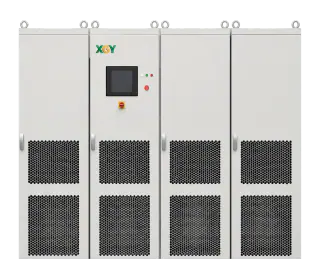
The current XGY MVGS selection guide lists configurable direct-medium-voltage output from 5 kV to 35 kV, standard capacity from 1 MVA to 10 MVA, and project expansion to 20 MVA and above. Published product material also lists four-quadrant operation and programmable ride-through, harmonic, and independent-phase functions. These are family-level selection facts, not a guarantee that every programmed waveform will appear unchanged at every DUT. Final topology, edge time, spectral accuracy, grounding arrangement, repetition rate, and protection behaviour depend on the selected configuration, output network, control setup, DUT load, facility interface, and acceptance method, and should be confirmed against the project test matrix.
FAQ
Frequently asked questions
Does front-end isolation mean the system has no transformer?
No. In the architecture discussed here, the isolation transformer is at the facility input rather than between the converter and the DUT. The output path still includes converter switching stages, filters, cables, switchgear, sensors, and protection, all of which must be included in the delivered-waveform assessment.
Can a step-up-transformer bench run LVRT profiles?
It can when the characterised source-plus-transformer path satisfies the required depth, duration, transition, phase, repetition, and uncertainty limits under the intended DUT load. Transformer frequency response, leakage impedance, residual flux, saturation margin, vector group, and source current limiting may narrow that envelope, so the answer must come from terminal measurements rather than topology alone.
Does direct MV output eliminate recovery waits between events?
It removes recovery time caused specifically by resetting an output transformer core, but it does not guarantee zero wait. Converter thermal limits, DC-link energy balance, semiconductor current limits, protection latches, discharge requirements, DUT reset behaviour, facility regeneration limits, and programmed sequence guards can still impose a minimum interval.
Why does transformer placement affect ground-fault testing?
An output transformer's vector group, neutral availability, winding capacitance, shields, and bonding become part of the DUT-side zero-sequence and common-mode network. Input-side isolation can make the output earthing scheme more configurable, but only the as-built single-line, impedance values, protection settings, and measured touch, residual, and common-mode quantities establish which fault tests are safe and valid.
Which architecture costs less?
A characterised step-up transformer can minimise capital cost when a suitable low-voltage source already exists and the required tests fit its verified transfer envelope. Direct-MV equipment may reduce fixture complexity or enable tests that the back-end path cannot meet. Compare total cost against the accepted test matrix, including measurement, protection, commissioning, energy, rework, and unavailable-test costs.
Keep exploring
Related technical resources
Related articles
Selection and Planning
How to Choose a Grid Simulator: 10 Specs That Matter
Voltage class, real vs apparent power, quadrants, edge speed, per-phase independence, harmonics, frequency range, grounding, protection, automation — the ten specifications that decide fitness, and the questions that expose them.
Read article
Application Test Guides
How to Test a Medium-Voltage SST at Full Power
The complete SST test bench, block by block: programmable MV grid interface, regenerative DC load or battery emulator, measurement and safety layer — plus the test matrix and an RFQ checklist.
Read articleTechnical Article
What Is a Solid-State Transformer (SST)? Architecture, Limits, and MVGS Testing
An engineering guide to solid-state transformer architecture, limits, and the role of a medium-voltage grid simulator in full-power SST validation.
Read article