
In brief
Low-voltage ride-through (LVRT) is a requirement for specified grid-connected equipment to remain connected and respond as defined during designated voltage dips instead of tripping immediately. HVRT covers specified overvoltage events, while ZVRT is the subset of low-voltage testing in which the applied terminal voltage reaches zero. The applicable code, equipment category, regional settings and connection agreement determine the envelope, permitted protection actions, any current-support requirement and the required recovery behaviour.
Key takeaways
- Ride-through exists because simultaneous disconnection of many converters can turn a cleared network fault into a larger generation or load imbalance.
- Ride-through curves define required operating regions and permitted actions across lower and upper voltage boundaries; use the assigned code and category instead of an 'above the line' shortcut.
- Where the applicable clause requires voltage support, reactive-current priority or active-power recovery, those behaviours need separate acceptance criteria; they are not universal ride-through rules.
- ZVRT removes or severely degrades the voltage reference at the measured terminals, so control mode, protection logic and recovery must be evaluated for the actual equipment design.
- Requirements differ by jurisdiction, equipment class, connection point and edition; test only against the controlled documents assigned to the project.
Why do grids demand ride-through at all?
The requirement was born from a failure mode. Early grid-tied inverters were programmed defensively: at the first sign of abnormal voltage, disconnect and protect yourself. Individually sensible; collectively dangerous. A transmission fault depresses voltage across a wide area for a few hundred milliseconds — and if every inverter in that area interprets the dip as its cue to leave, the grid loses a large block of generation at precisely the moment it is already stressed. The local fault has now been amplified into a regional generation deficit, with frequency and further voltage consequences cascading outward.
As inverter-based resources became material to system operation, connection rules increasingly defined disturbances during which assigned equipment must remain connected rather than disconnecting at the first abnormal sample. Some frameworks and equipment categories also prescribe voltage support, current priority, active-power reduction or recovery behaviour. Others use different response categories or permit particular protection actions. Reactive-current injection is therefore not an automatic consequence of the letters LVRT: it is a separate, clause-specific response that must be copied into the campaign basis exactly. Ride-through is not merely a dielectric survival test; it asks whether a defined configuration stays in the permitted state and produces the required response while the wider network clears a disturbance.
What does an LVRT curve look like?
| Envelope segment | What it defines | What the test record should show |
|---|---|---|
| Pre-event dwell | Nominal voltage, frequency, operating point and settling time | Stable initial conditions and the device configuration under test |
| Entry edge | How quickly voltage reaches the specified residual or overvoltage level | Delivered edge timing, phase behaviour and current response on one timebase |
| Event dwell | Required depth or height and the time for which it is sustained | Connection status, required current response where applicable, protection states and limit flags |
| Recovery boundary | The permitted trajectory back toward the continuous operating region | Voltage tracking, resynchronisation, active-power restoration and any overshoot |
| Post-event observation | The period in which delayed trips or unstable recovery can appear | Continued operation, settled power and a complete event log |
Read the envelope in segments, but do not infer the test from a chart alone. Depth describes the retained voltage at the declared reference point. Duration describes the interval between the defined entry and clearance markers. The recovery boundary may be a step, ramp or multi-segment trajectory, and the procedure may define whether phase angle changes, phase imbalance, frequency and source impedance are held constant. A separate behavioural clause may require continued operation, temporary current limitation, voltage support, reactive-current priority or a specified active-power recovery. Each requirement needs its own observable and decision rule; a generic instruction to “inject reactive current” is not enough to program or judge a test.
That behavioural layer is what makes ride-through a control-system and protection test as well as a withstand test. A run can remain connected yet fail a required response, or it can appear to recover while a delayed protection event occurs outside the plotted window. Conversely, a current response should not be judged against a rule that does not apply to that equipment category. The matrix must therefore separate connection state, current behaviour, protection state and recovery rather than compressing them into one “survived” verdict.
HVRT and ZVRT: the other two letters
HVRT mirrors the logic upward. Overvoltage events can follow load rejection, switching, resonant or lightly loaded network conditions and fault recovery, but the required envelope and response remain framework-specific. For the bench, the practical question is whether the selected source configuration can deliver the highest commanded voltage for the specified dwell while supplying or absorbing the DUT current without entering an undocumented limit. Published MVGS family data lists an optional -HV mode up to 1.3 times rated voltage. That is a configurable equipment boundary, not evidence that every MVGS configuration can execute every HVRT procedure or that 1.3 times rated voltage is a universal code requirement.
ZVRT is the subset of low-voltage ride-through in which the commanded voltage at the defined terminal boundary reaches zero for the specified phases and interval. A grid-following converter may lose the voltage signal used by its phase-tracking loop; a grid-forming converter, synchronous machine interface or plant controller can behave differently. The procedure decides whether zero applies to all phases, how residual voltage is measured, what phase relationship must exist on recovery and which trip or blocking actions are permitted. The source must demonstrate a sufficiently low residual voltage and the prescribed recovery under the actual DUT load. Transformer flux, source current limit, cable impedance, grounding and measurement noise can all make a programmed zero differ from the zero delivered at the reference point, so architecture is relevant but never a substitute for a measured pre-qualification run.
How do requirements differ by grid code?
The ride-through concept is universal; the parameters are not. Depth, duration, recovery shape, the reactive-support formula and the equipment classes covered all vary by jurisdiction and by edition. The table maps the landscape structurally — deliberately without quoting curve parameters, because standards revise and the only safe source for numbers is the current official text of the code your project connects under.
| Framework | Region | Ride-through scope | Verification note |
|---|---|---|---|
| IEEE 1547-2018 (with IEEE 1547.1 procedures) | North America (DER) | LVRT and HVRT by abnormal-performance category | Category assignment drives the applicable curves |
| AS/NZS 4777.2 | Australia / New Zealand (inverters) | Voltage ride-through with regional settings | Large-scale plant additionally faces NER / AEMO performance standards |
| EU Requirements for Generators (national implementations) | European Union | Fault ride-through framework by generating-module type | National implementation and system-operator rules complete important parameters and procedures |
| AEMO short-duration VDRT procedure | South Australia (defined historical supplementary scope) | Fast undervoltage disturbance stimulus and report evidence for the inverter scope stated by AEMO | Do not treat this bounded procedure as a current universal Australian LVRT profile |
How is ride-through actually tested?
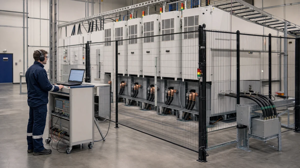
A ride-through test is the controlled reproduction of an approved event at an agreed electrical boundary while instruments capture both the delivered stimulus and the DUT response. Source edge time matters only in relation to the method’s tolerance and the loaded circuit: a command may change quickly while the voltage at the DUT terminals changes more slowly because of source control, current limiting, transformer behaviour or impedance. Published MVGS family data gives a voltage rise/fall specification below 1 ms, but a campaign still has to qualify the selected configuration with the intended interfaces and load range. Trajectory accuracy, phase behaviour, current headroom, energy flow and internal limit flags are equally important. Repeatability means that run identifiers, settings and raw data allow an independent reviewer to reconstruct each repetition; it does not mean that a source name or profile file alone establishes a valid test.
Can ride-through be tested at reduced voltage scale? Often for development, provided the claim is bounded. Controller hardware-in-the-loop, power hardware-in-the-loop and low-voltage prototypes can expose state-machine, phase-tracking, current-priority and recovery defects before a high-energy campaign. They do not automatically validate the production measurement chain, protection coordination, thermal state, actual current limit, insulation system or plant-level controls. Whether scaled evidence is acceptable for a formal decision is determined by the governing procedure and accepting body, not by this article or by the test-equipment supplier.
Turn the requirement into a controlled campaign
The expensive mistake is to begin with a library of curves and ask which one looks closest. A defensible campaign begins with the obligation and works toward the waveform. The output is a clause-to-event matrix in which every run has a reason, a controlled configuration, measurable acceptance criteria and a defined evidence package. A named standard is not enough because category assignments, local settings, connection agreements and test-body instructions can change which parts apply.
Freeze the basis and the test boundary
Record the document title, edition, amendment, clause, equipment category and any network-specific setting. Identify the legal manufacturer, DUT model and serial number, hardware revision, firmware build or hash, parameter file, active control mode and intended market. For a product family, obtain agreement on which variant is representative or worst-case for each event; the largest power rating is not automatically the worst case for control stability or protection timing.
Draw the single-line diagram and mark the point at which voltage is commanded, the point at which it is measured for acceptance and the point of common coupling relevant to the rule. Include transformers, cables, switchgear, grounding, neutral treatment, source impedance, DC source or load, plant controller, auxiliary supplies and protection interfaces. A profile proven at the simulator output is not necessarily proven at the DUT terminals, and an equipment-terminal test is not automatically a plant connection-point demonstration.
Convert each clause into an event row
For every required case, define the pre-event voltage and frequency, active and reactive operating point, power-flow direction, control mode, thermal state and dwell. Then define affected phases, retained or elevated voltage, entry transition, event duration, phase-angle behaviour, frequency behaviour, recovery trajectory, repetitions and post-event observation. If the method requires variation across operating points or phase patterns, create separate rows rather than hiding the sweep in an operator note.
The response columns should say what is observed and how it is calculated. Depending on the applicable clause, this may include connection state, cessation or blocking state, positive- and negative-sequence current, reactive-current increment, active-power priority, DC-link behaviour, protection flags, recovery time, overshoot or reconnection. Do not add a reactive-current target merely because it is common in another market, and do not omit it where the assigned category expressly requires it. Link every response to a calculation window, sign convention, filtering method, tolerance and owner of the conformity decision.
Qualify the setup before exposing the DUT
Run the planned events into an approved representative load or another safe qualification arrangement. At the acceptance boundary, verify the initial condition, residual or elevated voltage, transition timing, dwell, phase relationship and recovery. Exercise the maximum expected source and sink currents and inspect source limit flags, regenerative limits and protective transitions. Qualification at no load alone can miss the distortion that appears when the DUT demands current during the event.
Check the measurement chain at the same time. Confirm probe and transducer range, bandwidth, isolation, phase error, scaling, polarity, trigger latency, anti-alias filtering and time alignment. Preserve pre-trigger data and correlate the grid-simulator log, power analyser, oscilloscope, controller log and digital protection states. The AEMO short-duration VDRT procedure is a useful bounded example because it specifies the stimulus, operating condition, repetitions, instantaneous and RMS waveform reporting, power-output record and explicit pass/fail reporting. Its particular profile and historical application should not be transplanted into unrelated equipment or jurisdictions.
Execute, review and control changes
Give each run an immutable identifier linked to the matrix row and configuration manifest. Retain the commanded profile, measured source waveform, raw DUT channels, source status and limit flags, event logs, operator and witness record, analysis version and any deviation. A failed or invalid run stays in the inventory. Tuning firmware, changing protection or restarting a controller creates a new configuration and must not be concealed as a repeat of the original state.
After execution, reconcile the run list against the matrix, regenerate calculations from raw data and review borderline results with the declared uncertainty and decision rule. Close deviations through the route agreed with the laboratory, certifier, network party or internal design authority. Any later change to control firmware, settings, sensors, filters, power stage or protection logic requires an impact assessment against the affected event rows; a previous pass is evidence for an identified configuration, not a permanent property of a product name.
Measurement and evidence acceptance matrix
Two independent questions govern a ride-through result. First, did the bench deliver a valid stimulus at the specified boundary? Second, did the DUT satisfy every applicable response criterion? If the source clipped, the reference channel saturated or the timebases cannot be reconciled, the run is normally invalid or requires formal disposition; it should not be silently labelled a DUT pass or fail. The exact tolerances and guard bands come from the approved method.
| Acceptance object | Evidence to retain | Accept when | Hold, invalidate or investigate when |
|---|---|---|---|
| Initial condition | Terminal voltage and frequency, P and Q, control mode, temperature, DC condition and settled dwell | Every required precondition is inside its tolerance for the defined interval | The event begins during a ramp, limit, unsettled controller state or wrong power-flow direction |
| Delivered profile | Phase waveforms at the declared boundary, calculated residual or elevated voltage, entry time, dwell, phase behaviour and recovery | The complete loaded waveform meets the method, including the prescribed calculation method | Only the command is recorded, a channel clips, the source current-limits, or transformer and cable effects move the DUT waveform outside tolerance |
| Connection and protection state | AC current, contactor or breaker state, gate/block status, protection events and relevant communications flags | The DUT remains connected, ceases, blocks or trips exactly as the applicable clause permits | Connection is inferred from one noisy current trace or an undocumented protective action occurs |
| Support response, if required | Declared sequence quantities or per-phase currents, baseline, sign convention, calculation window, saturation and priority flags | The assigned response and timing meet the clause-specific rule with the declared decision treatment | A generic Q trace replaces the prescribed quantity, current clipping is ignored, or a non-applicable response target is imposed |
| Recovery | Voltage and current, active and reactive power, phase or frequency estimate, controller mode and delayed protection record | Required recovery occurs within its window without a prohibited trip, oscillation or overshoot | The plot ends at voltage restoration, masking delayed trips, repeated blocking or unstable power return |
| Traceability and repeatability | Run ID, sample identity, firmware and settings, procedure revision, raw files, instrument register, analysis version and deviation log | Each required repetition can be reconstructed and all changes are visible | Files were overwritten, failed runs disappeared, settings changed without a new manifest or plots cannot be regenerated |
Measurement uncertainty matters where a calculated response or timing result sits near a limit. Build the uncertainty treatment around the actual measurand: voltage ratio and bandwidth for the delivered profile; transducer magnitude and phase for sequence current or P/Q; trigger and sampling alignment for response time; and filtering or window placement for RMS quantities. A current calibration certificate does not resolve all of those effects. The campaign should state whether the rule supplies a conformity decision method or whether the accepting party has approved a guard band and an inconclusive region.
Failure modes that invalidate good-looking plots
- The command is mistaken for the stimulus. The programmed curve is plotted, but no independent terminal-voltage channel proves what the loaded DUT received.
- Residual voltage is measured at the wrong point. Transformer regulation, cable drop or switchgear impedance changes the event between the source and the declared boundary.
- Source saturation is mistaken for DUT current response. A current or regenerative limit reshapes voltage while the report attributes the resulting current entirely to converter control.
- A balanced event substitutes for an unbalanced requirement. Phase selection, sequence content, neutral path and recovery angle can exercise different controls and protection.
- Default functions remain hidden. Volt-var, frequency-watt, export limiting, current priority, plant control and protection act together, leaving the responsible function ambiguous.
- Reactive current is treated as universally mandatory. A response rule is borrowed from another category or jurisdiction instead of being traced to the applicable clause.
- The observation window ends at clearance. Delayed trips, oscillatory recovery, repeated blocking or slow active-power return disappear from the evidence.
- RMS processing erases the edge. Undocumented filters, window lengths or resampling soften the transition and move timing markers without preserving instantaneous data.
- A development retest overwrites the original failure. Firmware or settings are tuned between runs, but the report presents the final plot as if it belonged to the initial configuration.
- Equipment capability becomes a compliance claim. A simulator’s voltage, edge-time or profile feature is presented as proof that the DUT, laboratory or generating plant is certified or accepted.
These are evidence failures even when the hardware is undamaged. The remedy is usually procedural: measure at the agreed boundary, log source state, make functions and configurations visible, retain all runs and let the authorised decision-maker disposition deviations.
Applicability boundaries: what the result can and cannot prove
A valid bench run can show how the identified DUT configuration behaved under the recorded electrical conditions. A suite of valid runs can support type testing, design verification, model validation or a connection evidence package when the governing pathway accepts that use. It does not by itself establish that a laboratory is accredited for the method, that a certification body has approved the product, or that a network operator has accepted a generating system.
Small inverter products, megawatt PCS, grid-interactive UPS, wind or solar plant converters and grid-forming equipment should not share one generic ride-through matrix. Their standards, operating modes, current limits, auxiliary dependencies and plant-control boundaries differ. A battery PCS may need charge, discharge and zero-active-power cases. A UPS may have load continuity and bypass states. A generating plant may require evidence from equipment tests, RMS and EMT models, commissioning and site validation. The AEMO NEM connection process is relevant to that plant-level distinction; its role should not be collapsed into AS/NZS 4777.2 product testing or the older supplementary VDRT procedure.
Full-power, full-voltage testing is valuable when terminal voltage, current limit, protection, thermal state and recovery dynamics are central to the claim. Scaled testing is valuable when development speed, hazardous-energy reduction or controller coverage is the objective. Neither is automatically superior for every decision. State which physical effects are represented, which are simulated or omitted, and who has agreed that the evidence is suitable.
The same boundary applies to the test source. Released MVGS data supports discussion of a configurable direct-medium-voltage, four-quadrant platform, the listed rise/fall specification and optional overvoltage mode. Final suitability depends on the selected voltage and MVA configuration, short-duration current, load interaction, grounding, protection, interfaces, facility energy path and accepted procedure. Source qualification demonstrates delivered stimulus; it does not issue the DUT verdict.
Source-to-claim map
| Source | Claim supported here | Boundary retained |
|---|---|---|
| IEEE 1547 and IEEE 1547.1 | DER abnormal-voltage response is category-based and conformance procedures are distinct from the interconnection requirements | No category, curve value or market acceptance is assigned without the current documents and jurisdictional decision |
| AS/NZS 4777.2 | Relevant Australian and New Zealand inverter products have voltage-disturbance requirements and regional settings | The article does not extend product requirements to every plant or replace the applicable listing and network process |
| AEMO Short Duration VDRT Test Procedure | A bounded official example defines a fast disturbance, controlled setup, repetitions, waveform and power-output evidence, and explicit reporting | Its historical supplementary scope is stated; its numerical profile is not reproduced as a universal LVRT requirement |
| AEMO NEM connections guidance | Large generating-system acceptance can involve performance standards, models, studies and commissioning evidence beyond an equipment bench test | A bench result may support the package but is not represented as plant connection acceptance |
| EU Requirements for Generators | European fault-ride-through obligations sit within a framework completed by national implementation | No single Europe-wide parameter set is implied |
| XGY MVGS released product data | The family is configurable for direct MV, four-quadrant grid-simulation work and lists less-than-1-ms voltage rise/fall plus an optional 1.3-times-rated-voltage mode | No universal loaded-waveform performance, certification, accreditation or DUT compliance is claimed |
This map is intentionally conservative. It distinguishes a requirement source, a test-procedure example, a connection pathway and product capability data so that none is asked to support a broader conclusion than it actually carries.
Product fit
Where the MVGS fits
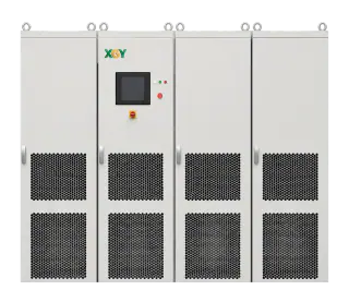
The XGY MVGS is a configurable four-quadrant medium-voltage source/load platform that can support programmed LVRT, HVRT and ZVRT workflows within the selected system's validated voltage, current, power, dynamic and regenerative envelopes. Published family data lists direct medium-voltage output, a voltage rise/fall specification below 1 ms and an optional -HV mode up to 1.3 times rated voltage; whether those figures satisfy a particular waveform at the DUT terminals depends on configuration, load, interfaces and the approved test method. The MVGS is one part of the bench and does not by itself establish compliance, laboratory accreditation or acceptance of the DUT.
FAQ
Frequently asked questions
What is the difference between LVRT and anti-islanding?
They pull in opposite directions, deliberately. LVRT requires equipment to stay connected through a grid disturbance; anti-islanding requires it to disconnect when the grid is genuinely gone and the equipment would otherwise energise an island. Compliance testing verifies both behaviours and, critically, that the equipment distinguishes the two situations correctly.
Does ride-through apply to energy storage and UPS, or just solar inverters?
Ride-through requirements can apply beyond solar inverters, including to energy-storage PCS and some grid-interactive UPS or other converter classes. A bidirectional PCS campaign may need charge, discharge and transition operating points, while a UPS may have load-continuity and bypass states. Applicability and the specific curves come from the assigned code, equipment category and connection arrangement.
Why is ZVRT considered the hardest ride-through test?
At a zero-voltage test point, grid-following controls may lose the terminal-voltage signal normally used for phase tracking, while grid-forming and other control modes respond differently. The DUT must take only the protection actions permitted by the applicable procedure and recover as specified when voltage returns. The source must also demonstrate the commanded residual voltage, phase conditions and recovery at the agreed DUT measurement boundary.
Can I take ride-through curve parameters from this article?
No — deliberately. Depth, duration and support requirements vary by jurisdiction, equipment class and standard edition, and they change on revision. Take parameters only from the current official text of the code your project connects under, and have the applicable category confirmed as part of the compliance plan.
Keep exploring
Related technical resources
Related articles
Application Test Guides
Grid Code Compliance Testing: 1547, UL 1741, 4777.2
The standards landscape for grid-connected equipment — IEEE 1547/1547.1, UL 1741, IEC 62116, AS/NZS 4777.2 and AEMO requirements — what a campaign contains, and why capability is never certification.
Read article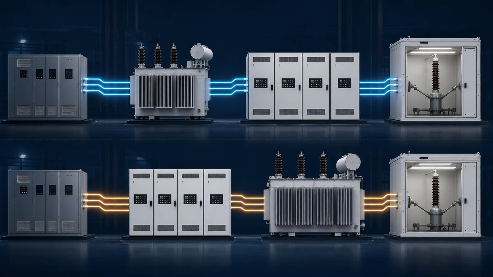
Isolation, Grounding and Safety
Front-End vs Back-End Isolation in MV Test Systems
Transformer placement changes the source-to-DUT transfer path, grounding options, fault response, and evidence required for medium-voltage testing.
Read article
Grid Simulator Fundamentals
What Is a Grid Simulator? A Plain-English Guide
A grid simulator is a programmable AC source that reproduces grid behaviour — sags, swells, harmonics, ride-through events — for lab testing. What it does, who needs one, and how to spec it.
Read article