
In brief
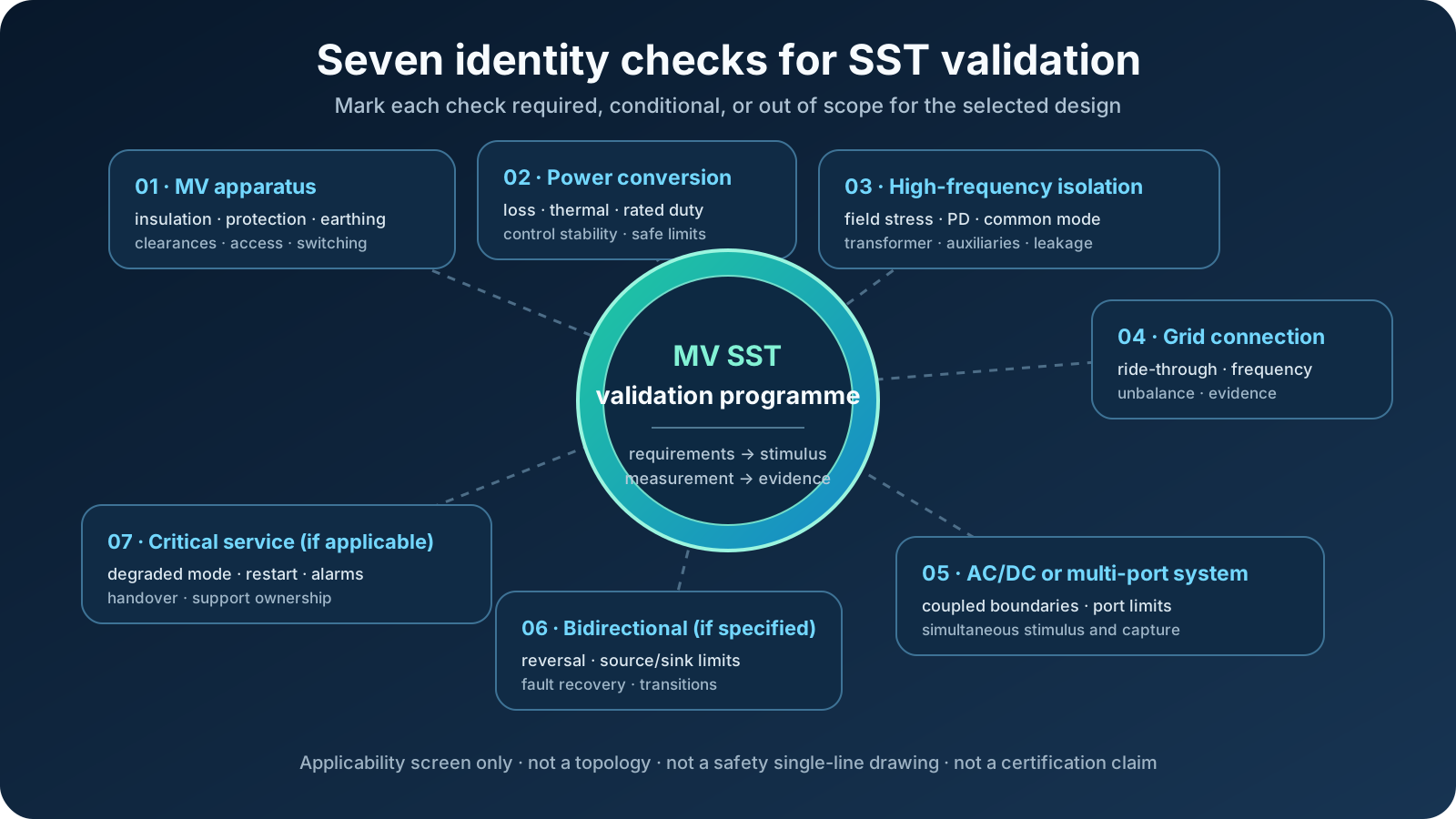
A medium-voltage solid-state transformer is difficult to test because one design can combine several demanding roles: medium-voltage apparatus, high-power conversion, high-frequency isolation, grid connection, multiple actively controlled ports, bidirectional operation and critical-infrastructure service. Not every SST has all seven. Validation begins by marking each identity as required, conditional or out of scope for the actual topology, then testing the interactions with the appropriate mix of simulation, component work, scaled platforms and full-voltage or full-power evidence.
Key takeaways
- Use seven identity checks — MV apparatus, power conversion, high-frequency isolation, grid connection, multi-port conversion, bidirectionality and critical service — and record which ones actually apply to the selected SST.
- Every active electrical boundary in scope needs a defined stimulus and simultaneous evidence; for a typical MVAC-to-DC or LVAC design this means coordinating the MV input with the opposite-port operating condition.
- A utility connection is not a programmable laboratory source; deliberate ride-through, phase-jump, unbalance, harmonic and fault cases require an authorised, engineered test boundary.
- Where claimed or applicable, active current limiting, DC fault protection, restart logic and module bypass each need explicit criteria and evidence.
- Where multi-cell construction is used, it adds a control-layer campaign covering voltage balance, current sharing, communication loss, module failure and thermal imbalance.
Which of the seven test identities apply?
Start with an identity screen, because everything else in the programme follows from it. Ask seven questions of the actual design: is the test article medium-voltage apparatus; what power-conversion and thermal envelope applies; where is high-frequency isolation used; is it grid connected; which AC and DC ports are actively controlled; is power flow bidirectional at any port; and does the intended service impose critical-infrastructure availability or recovery requirements? Record each answer as required, conditional or out of scope, with a document owner.
Not every SST answers yes to every question. A unidirectional two-port design should not inherit bidirectional cases, and a development demonstrator should not be assigned production-service availability criteria by default. The difficulty is the conjunction of the identities that do apply: insulation, converter control, protection and grid-compliance engineers can each write a different plan for the same assembly, yet the applicable plans must run on shared equipment inside one safety boundary and project schedule.
| SST demand axis | Test question | Evidence needed |
|---|---|---|
| Medium-voltage input | Does insulation and protection remain controlled across the operating envelope? | Withstand, leakage, protection-state and calibrated voltage records |
| High-power conversion | Are losses, thermal limits and controls stable across the declared duty? | Power-analyser data, thermal trends and repeatable steady-state points |
| High-frequency isolation | Does the transformer insulation tolerate repetitive converter stress? | Design-specific insulation and partial-discharge evidence |
| Grid connection | Does the SST behave correctly during sags, swells, frequency events and unbalance? | Time-aligned input waveforms, status logs and pass/fail criteria |
| AC/DC or multi-port conversion | Are interactions between electrical boundaries controlled? | Simultaneous input/output waveforms, port limits and cross-coupling records |
| Bidirectional operation, if specified | Are power reversal, port limits and recovery transitions controlled? | Operating-envelope points and transition records in every required direction |
| Critical-infrastructure service, if applicable | Can faults, maintenance and recovery be managed without hidden single points of failure? | Protection selectivity, degraded-mode, restart, alarm and handover evidence |
High voltage, high power, high stakes
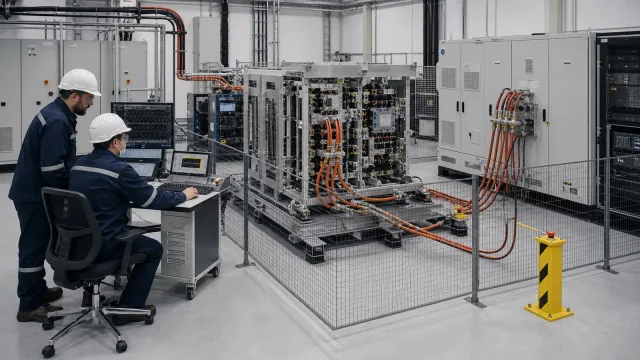
The first identity sets the physical scale of everything that follows. Depending on application and topology, an SST may connect within part of the medium-voltage distribution range and operate at hundreds of kilowatts, megawatts or above. A laboratory that hosts a full-scale device is therefore an installation, with suitable switchgear, engineered protection and earthing, interlocked access, and cooling matched to the actual loss envelope. Stored energy in DC links and fault energy available at the terminals can be far beyond ordinary bench-source conditions, which makes safety engineering a design discipline. Facility readiness, interfaces and responsibilities belong on the critical path of the full-power SST bench plan, not in a checklist added after the converter arrives.
Why must every active boundary be tested?
An SST with two or more actively controlled electrical boundaries needs a defined condition and suitable instrumentation at each boundary in scope. A common full-power arrangement is a chain: a programmable medium-voltage grid interface feeding an MVAC port, and a controllable DC- or LVAC-side system absorbing or shaping the opposite-port condition. Other topologies require a different set of sources, loads and emulators. Around the selected chain sits the measurement and safety layer: power analysers, high-voltage probes and oscilloscopes, insulation monitoring, protection and interlocks, thermal instrumentation and test automation.
For a design with coupled active ports, characterisation from one side alone cannot demonstrate the coupled system behaviour: input ride-through response depends on the opposite-port operating point, and output regulation depends on input conditions. Test plans that stimulate the boundaries independently can miss interactions that matter in service. The complete bench architecture therefore treats the programmable MV side, controllable opposite-port source/load, measurement and protection as separate but coordinated scopes.
What events does the input side need — and why can’t the grid provide them?
Where the grid-connected identity applies, the input-side matrix can be extensive: voltage sags and swells across programmed depths and durations; low-, high- and zero-voltage ride-through profiles where required by the applicable grid code; frequency variation and rate-of-change-of-frequency events; phase jumps; three-phase unbalance; harmonic and inter-harmonic injection; phase-specific events; authorised fault cases; and grid-impedance changes where stability against weak-grid conditions is in scope.
A utility connection is appropriate for authorised commissioning and normal-operation studies; it is not a programmable laboratory stimulus. Deliberate faults, phase jumps, unbalance and harmonic conditions require an engineered test boundary, and natural grid events cannot provide controlled parameters or repeatable before/after comparisons. This is the gap a programmable grid simulator is intended to close. For SST work, the specified event must be verified at the DUT terminals under the declared load and measurement bandwidth: a source catalogue edge time or per-phase-control statement is an input to the bench design, not proof that the required waveform arrived undistorted.
Why isn’t steady-state efficiency enough on the output side?
Because the load the SST will actually serve may be nothing like a resistor. An AI data-centre power system can present rapid changes, management-plane power limits, energy-storage interactions and aggregated behaviour across many racks. The applicable profile depends on the computing architecture and control policy; it must be measured or specified rather than copied from a generic “AI rack” curve. An SST that regulates well into a static load bank can still respond differently to dynamic operation because control loops, DC-link energy management and protection thresholds are exercised during transitions.
A credible output-side programme therefore includes programmed dynamic profiles derived from the target application, not only efficiency mapping. Efficiency maps still matter, but they are the beginning of output-side testing, not the end. The conclusion for bench design is simple: budget opposite-port equipment and instrumentation that can execute and record the required profiles, not just absorb steady watts.
What do insulation, grounding and common-mode add?
Where high-frequency isolation is part of the selected design, it introduces test families that scaled work cannot fully reproduce. At the design voltage, the programme can need to address insulation coordination across the assembly; the medium-frequency transformer’s repetitive converter stress; charge-based partial-discharge measurement where applicable; common-mode voltage and leakage-current paths; the grounding topology of converter, enclosure and test system; line-to-PE fault behaviour; and isolation of auxiliary and control circuits. A scaled prototype may reveal control and topology problems, but it does not reproduce the final field distribution, insulation construction or partial-discharge inception margin. IEC 60270 supplies a general charge-based measurement framework; the SST’s product and insulation design still determine the procedure, stress waveform and acceptance limit. The isolation-architecture guide explains why the test source and isolation boundary must be considered together.
How is semiconductor fault behaviour different — and what must be tested?
A conventional transformer limits downstream fault current largely through passive impedance while coordinated protection clears the fault. An SST relies more directly on sensing, control and semiconductor protection, whose allowed fault-current magnitude and duration are design-specific and can be much shorter than electromechanical clearing times. That behavioural difference can enable active current limiting, but it also creates a test burden. The fault campaign must explicitly verify: short-circuit response at each required port; current-limiting accuracy and stability; DC-side fault protection, where the absence of natural current zeroes complicates interruption; fault isolation between ports; restart sequencing after clearance; any claimed module bypass and derated continuation; and operation within the selected devices’ safe operating areas. These cases need deliberate, instrumented fault injection inside an engineered boundary; many are unsuitable for a live grid or production data hall.
Why does modular construction multiply the test matrix?
Many medium-voltage, high-power SST architectures use power cells in series, parallel or both — one route to distributing voltage and power across available devices. Where the selected design is modular, it adds a control-layer campaign on top of everything above: cell voltage balancing across a series string; current sharing among parallel paths; phase synchronisation; behaviour under communication loss; response to a module failure, including detection, bypass and any claimed redundancy or derating; and thermal imbalance as cells and cooling paths differ. These system-level behaviours cannot be demonstrated on one cell. Communication-loss and module-failure cases should be exercised deliberately on a protected bench whenever the design claims controlled degraded operation.
What should be frozen before equipment is quoted?
Turn the seven identities into a requirements-to-evidence matrix before selecting the source, load or instruments. For every planned case, record the requirement owner and document; hardware, firmware and parameter-set identity; electrical boundary and operating point; stimulus at the DUT terminals; simultaneous quantities and states to capture; calculation window and uncertainty treatment; protection and safe-state expectation; pass/fail authority; and the raw-file, plot, log and report identifiers that will close the row. This prevents a common late discovery: the bench can create an event, but cannot prove what the project actually needs accepted.
Freeze scope boundaries at the same time. State who supplies the MV switchgear and cables, opposite-port source/load, cooling, grounding design, instrumentation, calibration, automation, interlocks and FAT/SAT procedures. Record which requirements will be answered by simulation, hardware-in-the-loop, component testing or full-power testing, with a reason for each allocation. The five-method comparison helps keep cheaper development methods in the programme without allowing them to stand in for a boundary they cannot reproduce.
So what does it take?
Pull the applicable identities back together and the shape of the answer is visible. A full-scale SST validation system can include a programmable medium-voltage grid interface sized for the required input events; controllable sources, loads or emulators on the other active ports; a measurement and safety layer designed for the selected voltage and power; and a traceable plan that sequences insulation, control, fault and grid-interaction work across shared equipment. Simulation, hardware-in-the-loop, component testing and scaled benches retain legitimate roles throughout development. Full-voltage or full-power testing should be reserved for the requirements whose physical boundary makes it necessary, with the applicable authority agreeing what evidence is ultimately required.
Product fit
Where XGY Tek fits
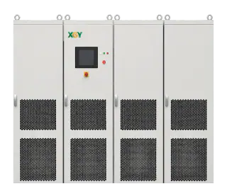
Where the selected SST exposes an MVAC test boundary, XGY Tek can configure the MVGS as its programmable medium-voltage interface, with voltage, apparent-power, power-flow and disturbance requirements reviewed against the programme. The complete bench still requires suitable opposite-port sources, loads or emulators plus specialist instrumentation, protection and facility engineering; those interfaces and responsibilities should be defined at quotation.
FAQ
Frequently asked questions
Can an SST be validated on a scaled low-voltage prototype?
Partially. Scaled prototypes are valuable for topology, control and selected fault or multi-module studies when the scaling law and omitted boundary are explicit. They do not by themselves demonstrate the final design's full-voltage field distribution and partial-discharge margin, full-rated thermal performance, or protection coordination at the final available fault energy. Allocate each requirement to the least costly method that reproduces the physical boundary it depends on.
Why not test an SST by connecting it directly to the utility grid?
Direct utility connection suits authorised commissioning, normal-operation and long-duration steady-state work. It is not a controllable source for deliberately repeating ride-through events, phase jumps, unbalance, harmonic injection or fault cases. Those cases need a programmable source inside an engineered protection and measurement boundary, with the required approvals.
What is the single hardest SST test family?
There is no universal answer, but two families deserve early attention: partial-discharge and insulation behaviour of the medium-frequency transformer under its actual repetitive stress; and DC-side fault protection, where there is no natural current zero and converter protection must act within the limits of the selected semiconductor system.
Does one instrument cover SST testing?
No single instrument covers every applicable identity. A full-power, multi-port SST bench can require a programmable MV interface, a suitable source/load on each opposite port, and a measurement and safety layer around the complete system. The exact blocks depend on the selected topology, directions of power flow and evidence plan.
Keep exploring
Related technical resources
Related articles
Application Test Guides
How to Test a Medium-Voltage SST at Full Power
The complete SST test bench, block by block: programmable MV grid interface, regenerative DC load or battery emulator, measurement and safety layer — plus the test matrix and an RFQ checklist.
Read article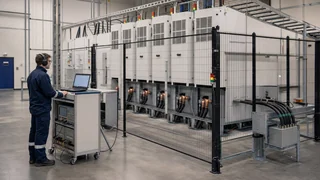
Technical Article
What Is a Solid-State Transformer (SST)? Architecture, Limits, and MVGS Testing
An engineering guide to solid-state transformer architecture, limits, and the role of a medium-voltage grid simulator in full-power SST validation.
Read article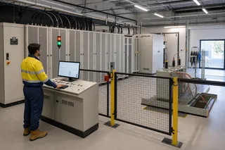
Grid Simulator Fundamentals
What Is a Grid Simulator? A Plain-English Guide
A grid simulator is a programmable AC source that reproduces grid behaviour — sags, swells, harmonics, ride-through events — for lab testing. What it does, who needs one, and how to spec it.
Read article